|
|
|
Elevating the Collection Construction Photo Gallery
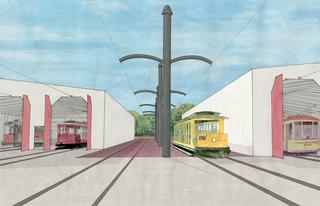
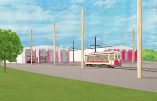
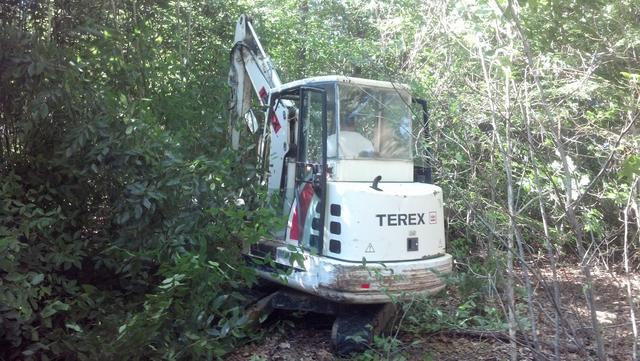
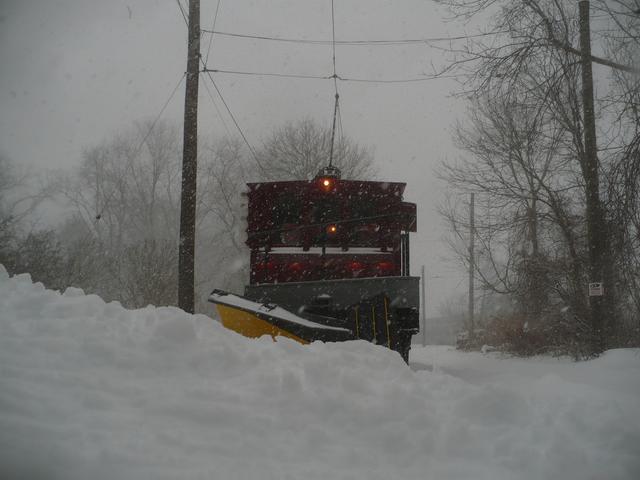
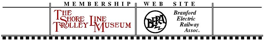
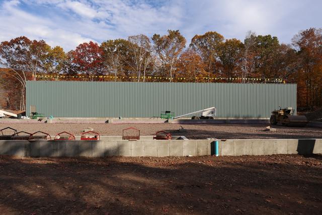
The Shore Line Trolley Museum's priceless and irreplaceable
collection of antique trolley cars will soon be safe from future coastal
floods such as Irene (pictured above) and Sandy. This page is an archive
of construction photos of Elevating the Collection.
You can help us reach our $2 Million goal which will fully fund the
installation of tracks and live wire to reach the new buildings.
Email us or call (203)467-6927 for more information.
LATEST UPDATE
|
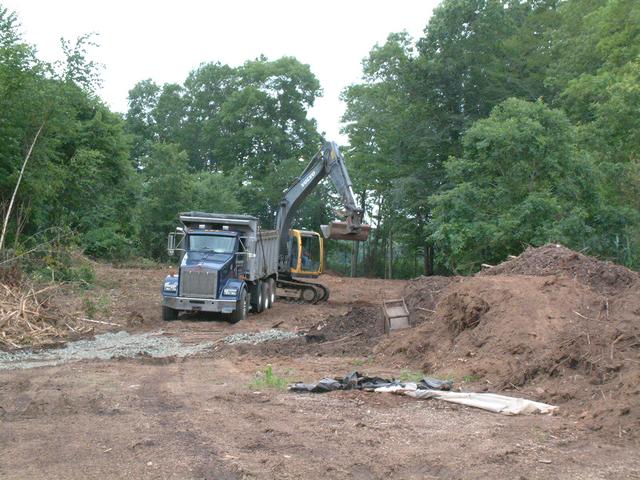
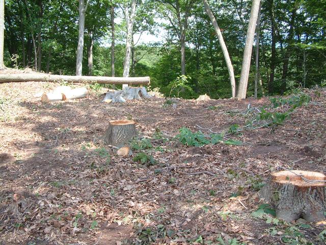
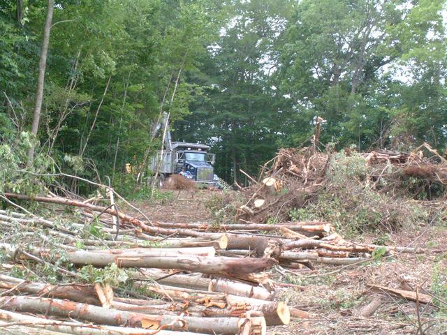
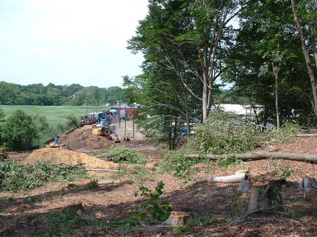
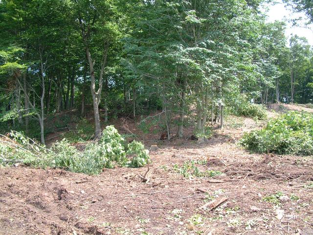
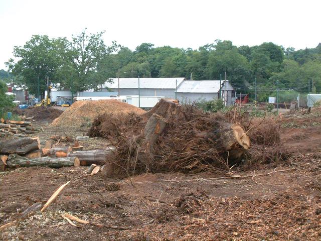
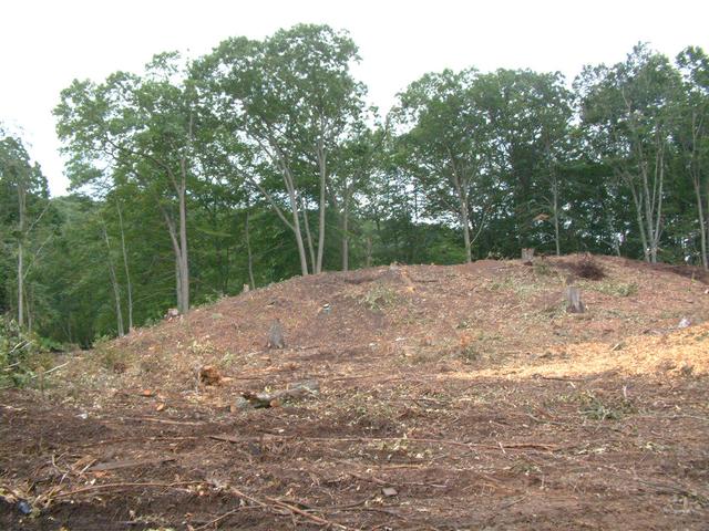
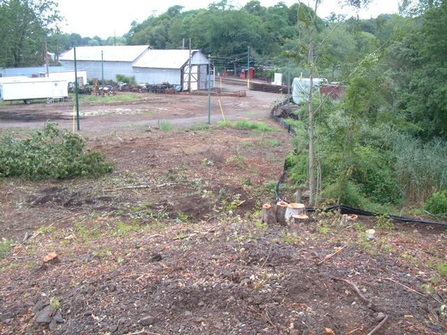
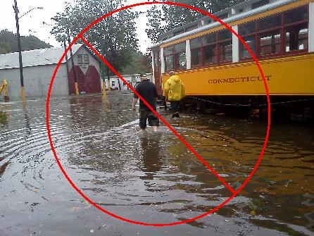
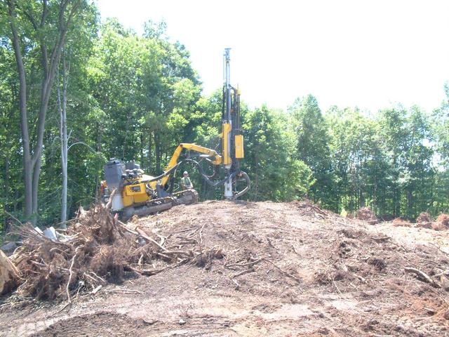
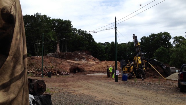
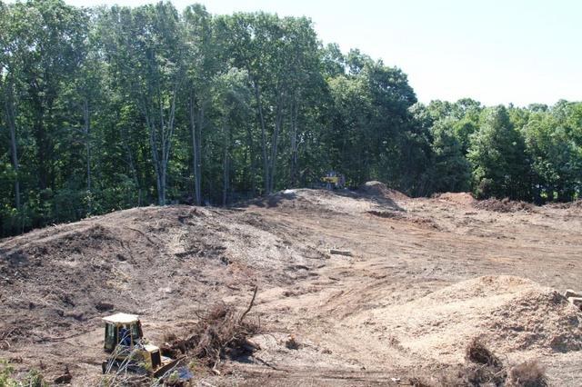
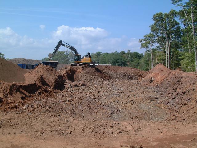
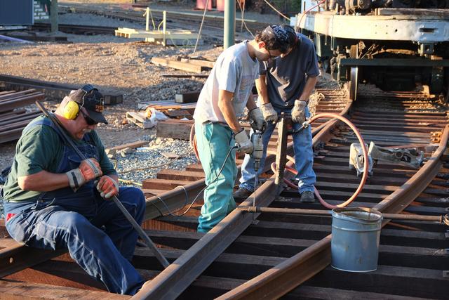
Having a Blast, Wish You Were Here
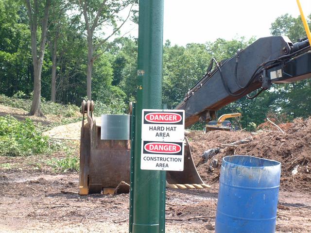
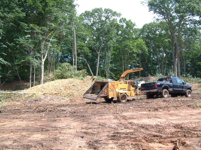
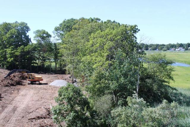
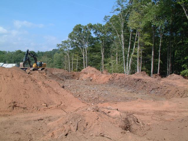
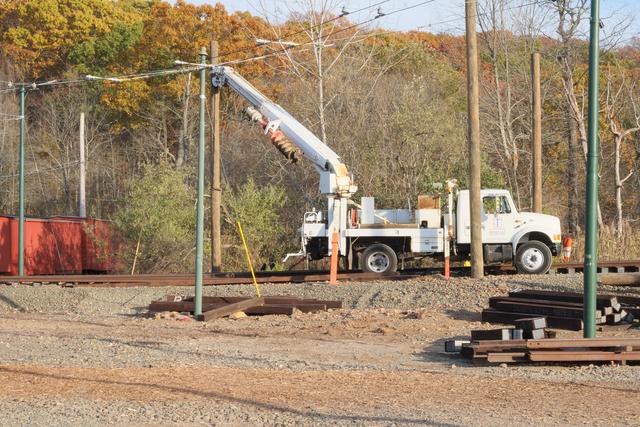
With trees and stumps cleared from the construction area, blasting
operations began at the beginning of August. This drilling rig has
a water-cooled, carbide-tipped 2 inch hammer drill. It takes only a few
minutes for it to drill down the 10-20 feet needed. Most of contract building
1 is above ledge and requires blasting, to a depth sufficiently below the
planned floor elevation to allow for required foundation depth. Almost all
of contract building 2 requires filling to achieve the elevation. The excess
material cut from the hill will be used, in part, to fill where needed.
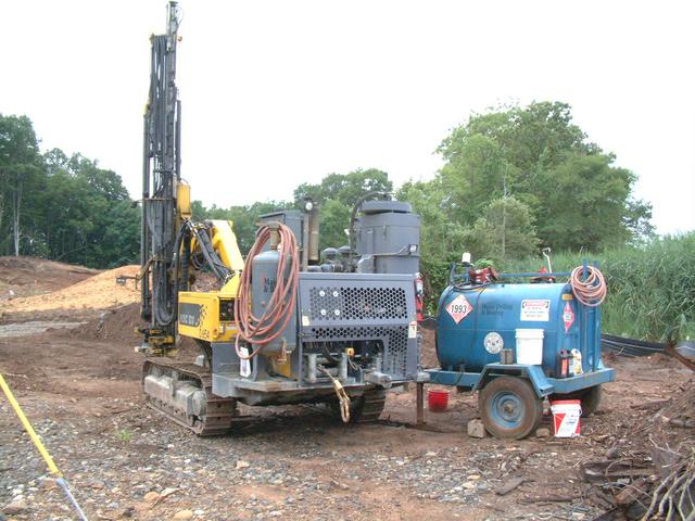
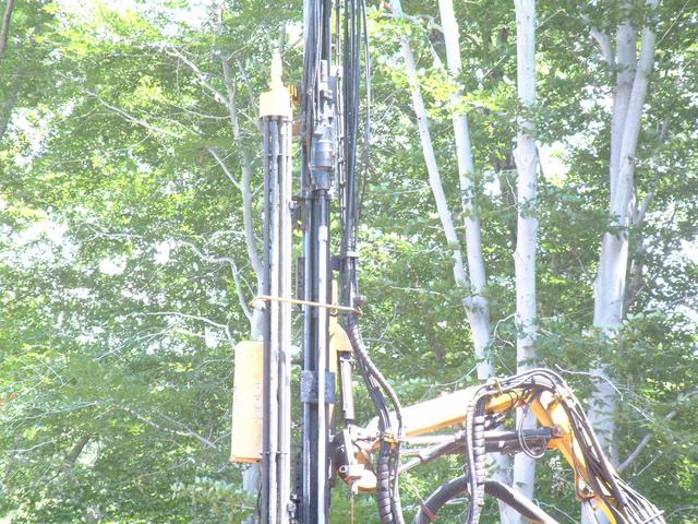
The drill rig is hydraulically controlled. The actual drilling motor
is near the top of the mast. The structure to the left of the mast contains
the extension rods.
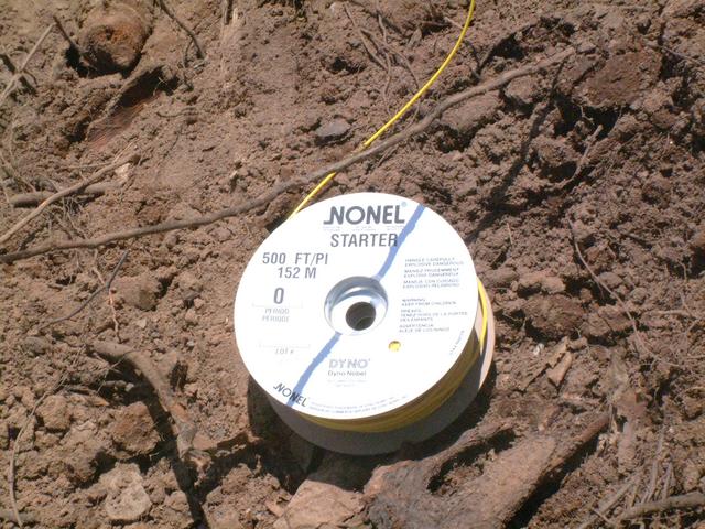
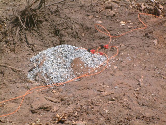
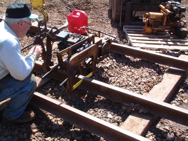
Having watched too many Roadrunner/Coyote cartoons, many of us were hoping
to see two wires leading to the "ACME" trigger box! Modern blasting is
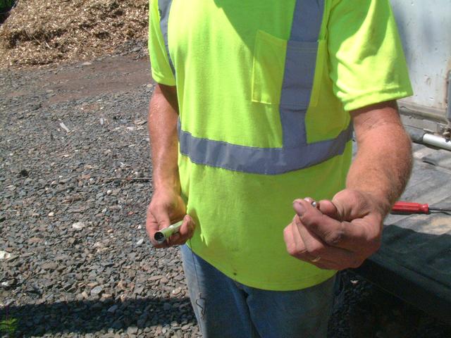
not controlled electrically or via radio anymore. The trigger is this small
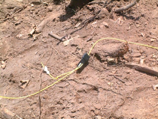
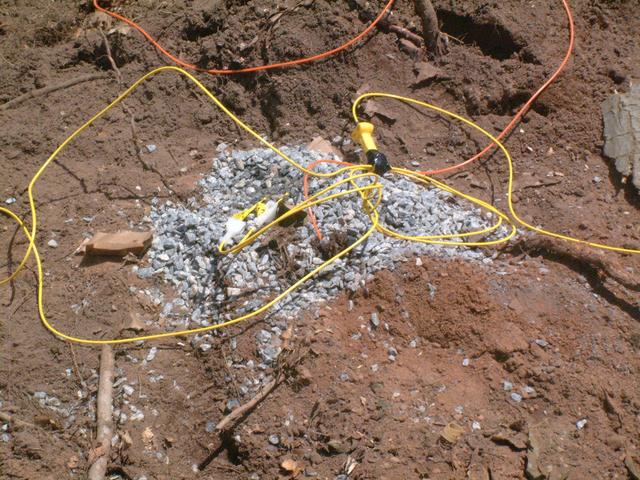
hollow plastic tubing which is filled with powder. The yellow lines connect
to other yellow lines via the powder-filled junctions. In turn these
connect to the orange lines which lead to the bottom of each drilled hole.
The hole is filled with an explosive slurry mixture and then rammed with
crushed stone to help contain and direct the blast. By adjusting the length
of the lines, a controlled staggered firing delay is created which affects
how the rock will break up.
These funnels are used to load the holes with the explosive mix.
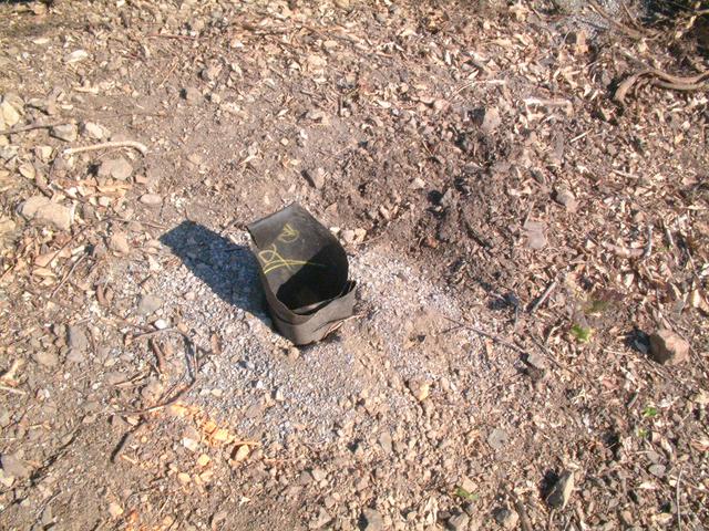
The whole thing is triggered by a spring-loaded plunger which strikes this
small shotgun primer cap and sends the initial explosion into the yellow
fuse line.
Click on the image above to download a small
video of the actual blast
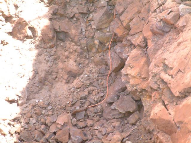
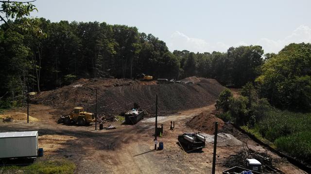
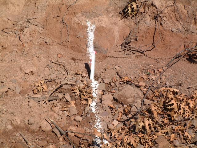
After the blast, the contractor excavated the overburden (loose soil) and
broken rock until reaching the edge of the blasted rock. The remnants of the
orange trigger line can be seen at the bottom of the crater. The pile of
rock gives an idea of the range of sizes into which the rock fractures.
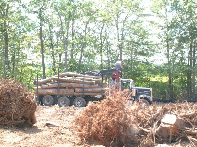
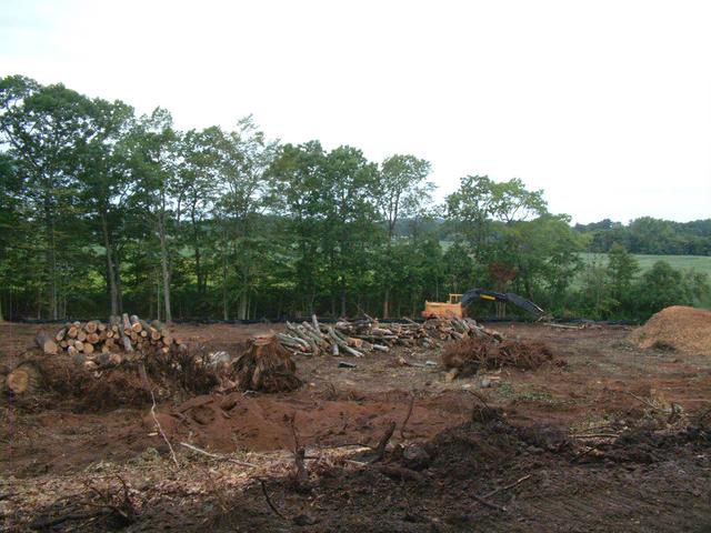
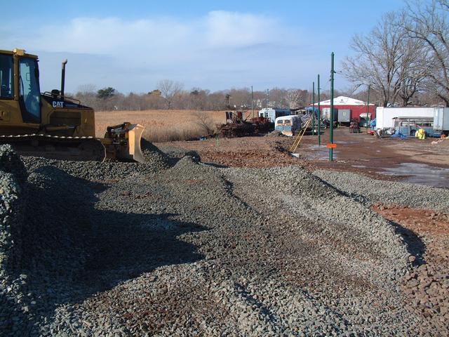
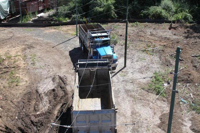
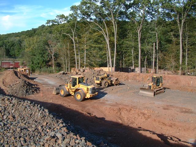
After each blast, construction vehicles are busy moving earth and continuing
to truck away unusable materials and debris.
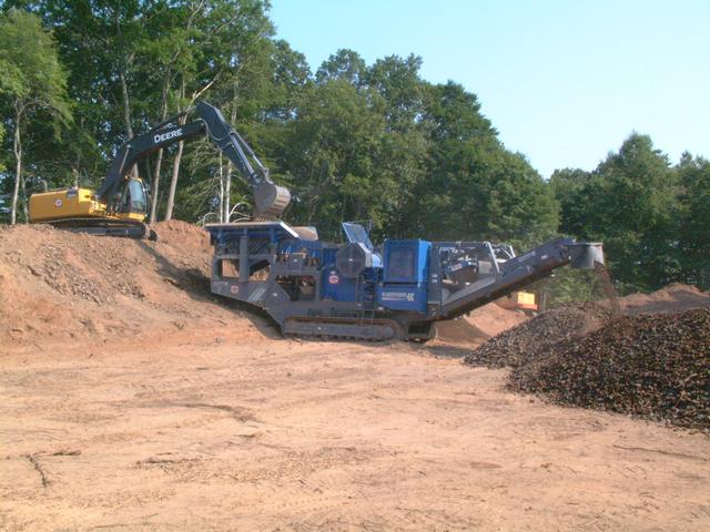
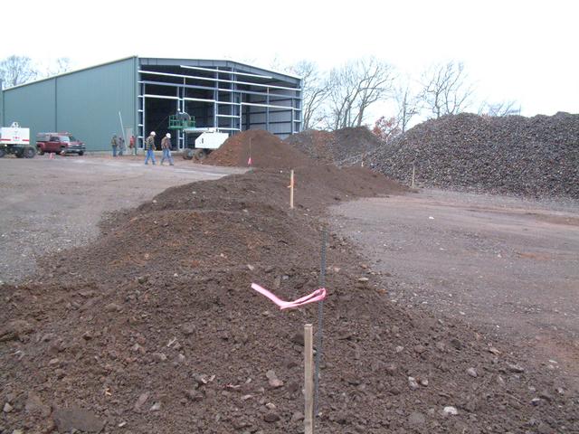
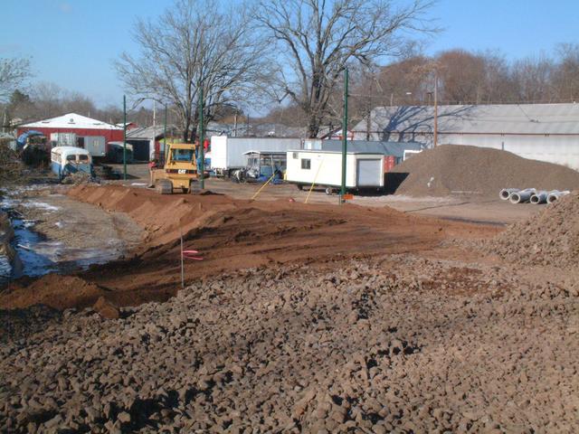
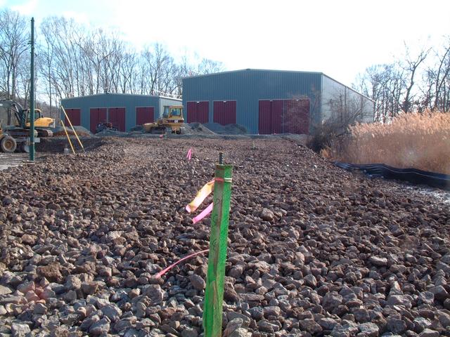
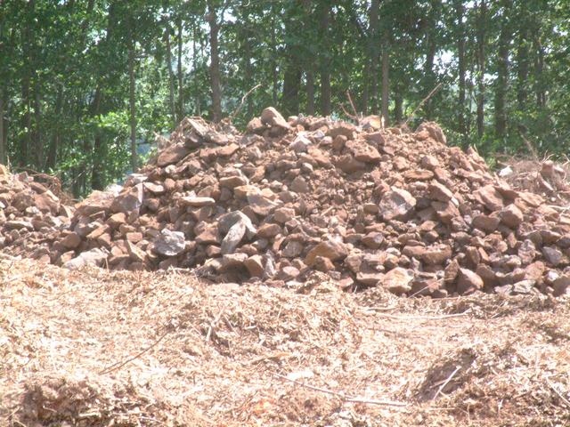
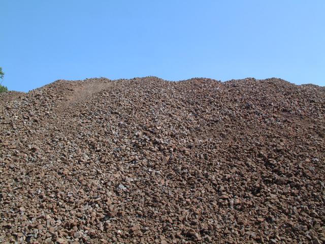
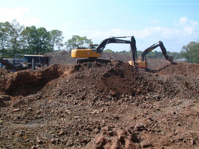
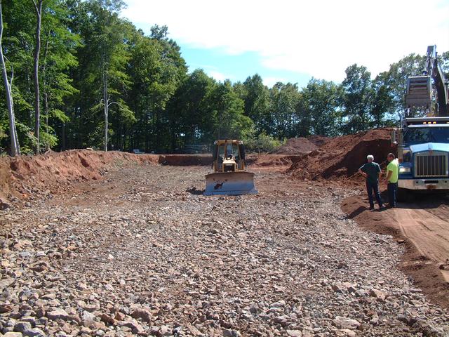
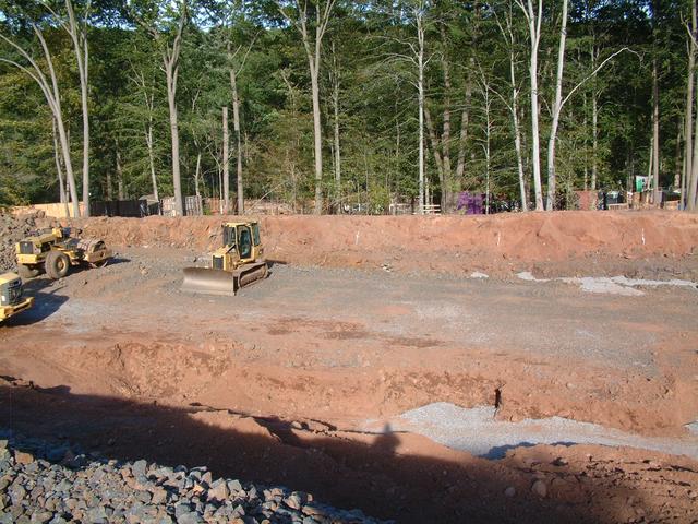
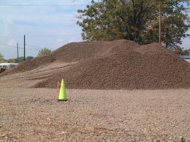
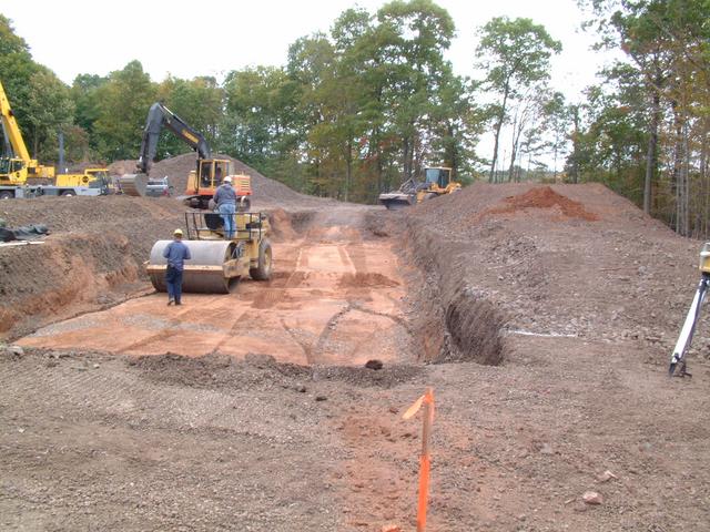
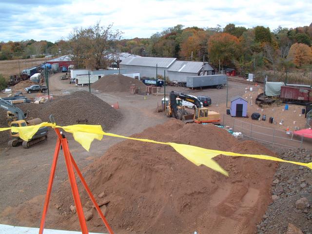
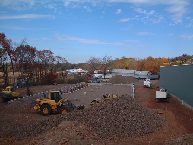
Crushing Nears Completion
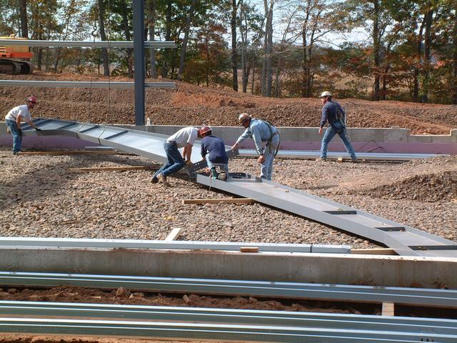
Sep 1, 2013: After a week of crushing we are almost done processing the
blasted rock, which has created a mountain of crushed stone!
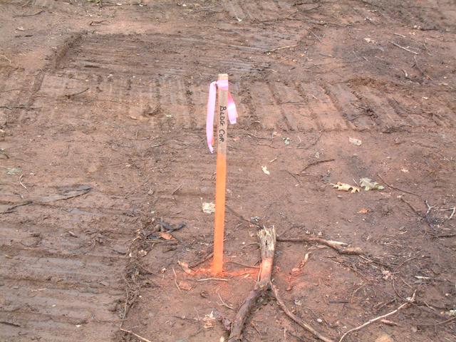
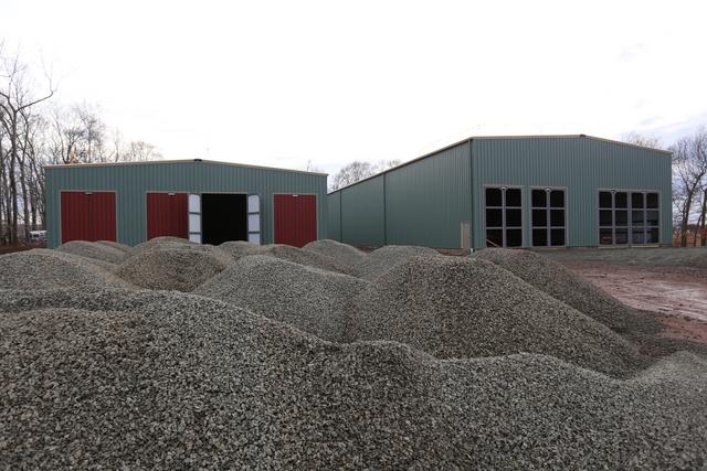
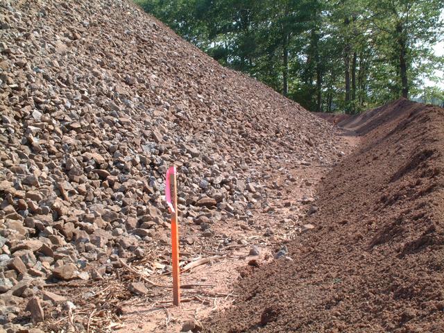
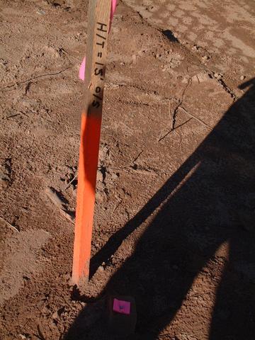
The crushed stone is being stockpiled in the footprint of new building number
2, adjacent to the blasted area which new building number 1 will occupy.
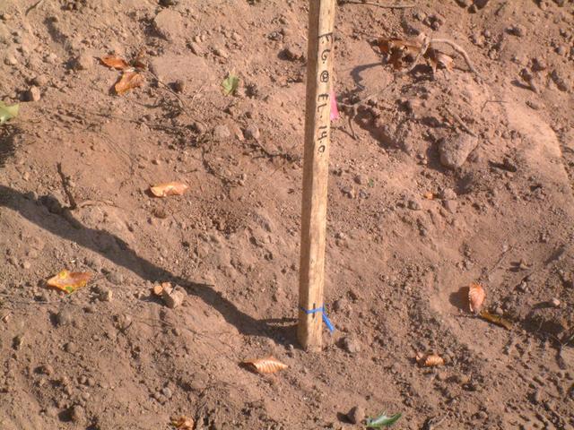
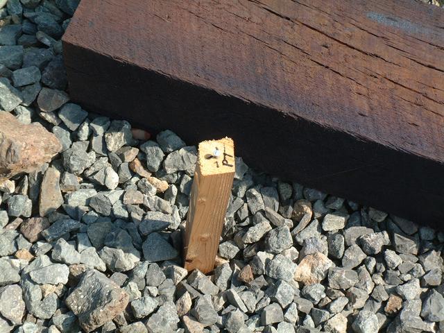
The stake represents the front right corner of building 2.
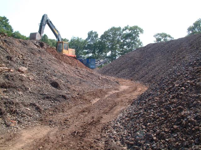
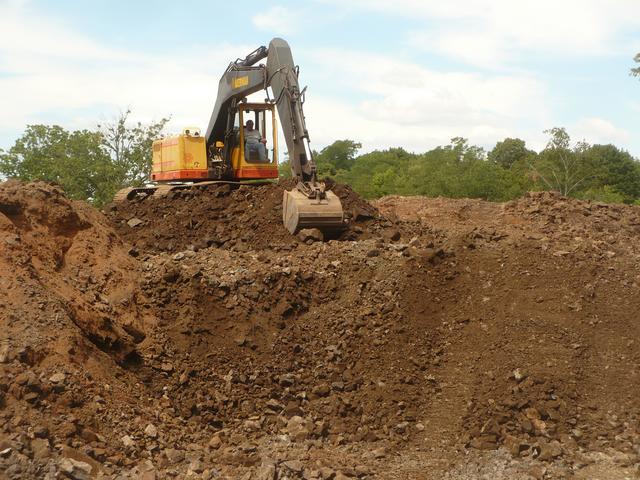
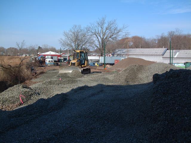
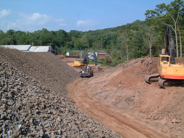
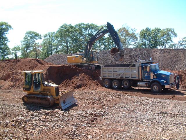
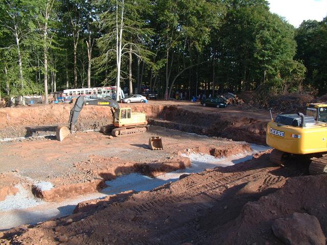
Looking across the excavation for building 1, blasted stone is being
loaded into the crusher. Two excavator machines are needed to keep things
moving, along with a few loaders to stockpile the crushed stone.
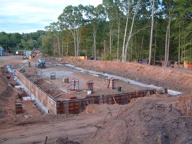
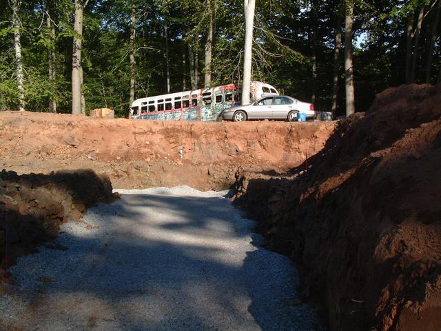
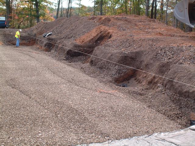
Looking towards the back of new building 1. The surrounding grade is
approximately the height of the track/floor. The excavation is about 5
feet deep. By about September 6, excavation for the
footings of the building foundations will begin.
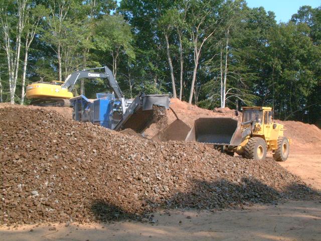
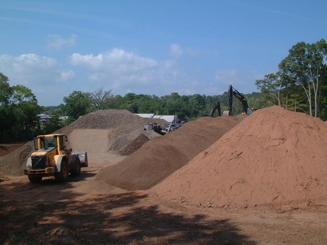
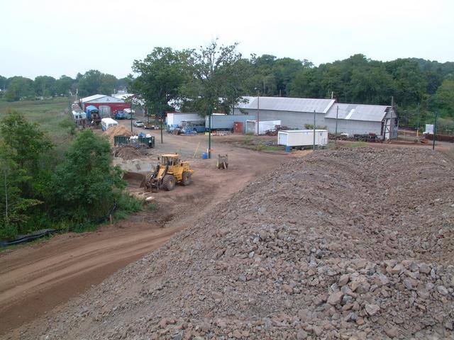
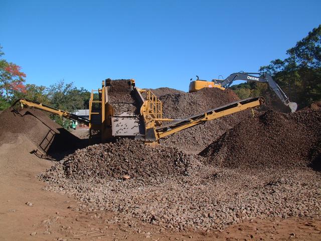
The mountain of crushed stone is over 30 feet high. When crushing is
completed in the next few days, we will have almost 10,000 cubic yards of
crushed stone. It will then be screened and stockpiled in three categories:
coarse sub-ballast, ballast, and processed fine gravel. A lot of this material
will be used up in filling the low parts of the project to the required
elevation, including the track approach ramps. Still, we expect to have
a significant amount of track ballast stone left over.
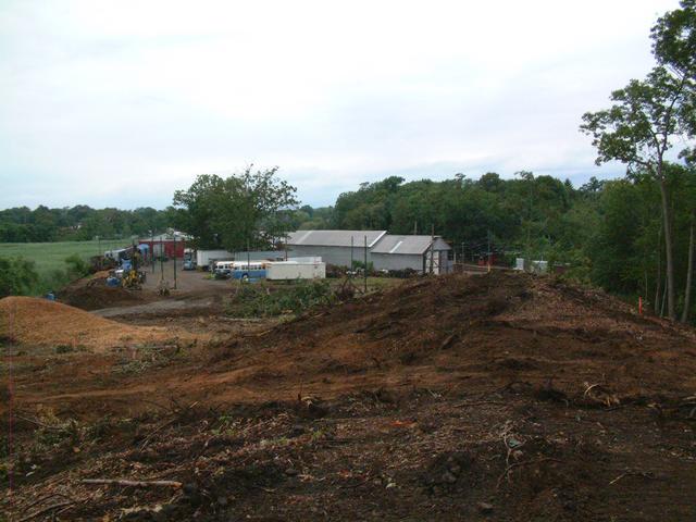
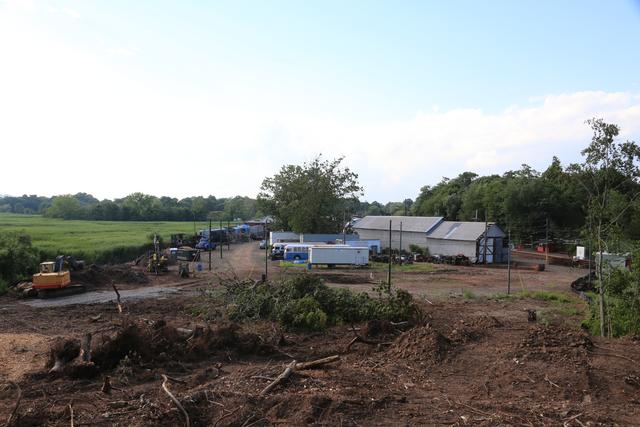
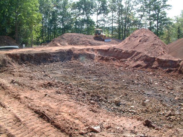
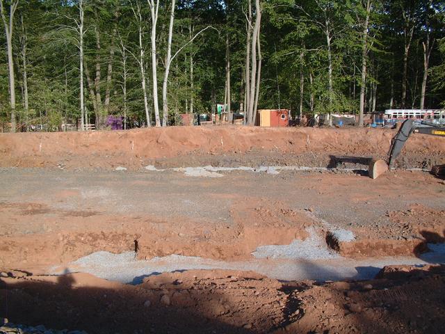
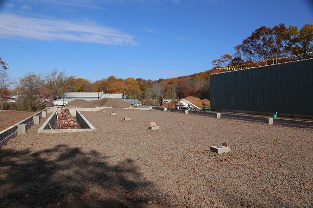
The Stake-Out
As we move into September, the crushing operation has concluded.
It's hard to believe that this large, flat, open area was once
a small mountain.
The crushed stone will be screened into three different sizes and
temporarily stockpiled in the open area behind the E.H. Blossom Barn.
Much of the stone will be used in filling and grading in and around
the buildings and approach tracks. We expect to have a considerable
amount left over for future track maintenance use. Because space is
very limited, excess red sandy soil is being taken away by the contractor.
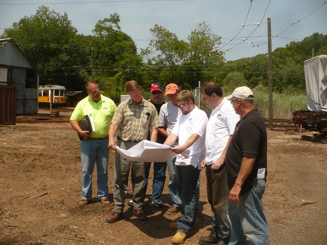
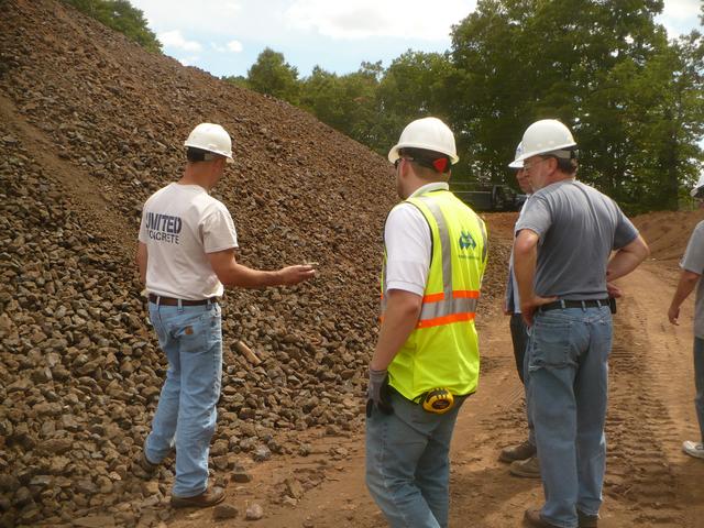
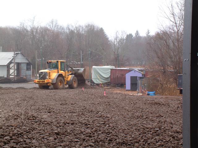
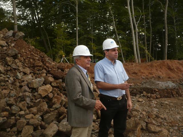
Town of Branford First Selectman Anthony "Unk" DaRos (l) takes a tour of the
construction site with museum President Jeff Hakner.
 ;
;
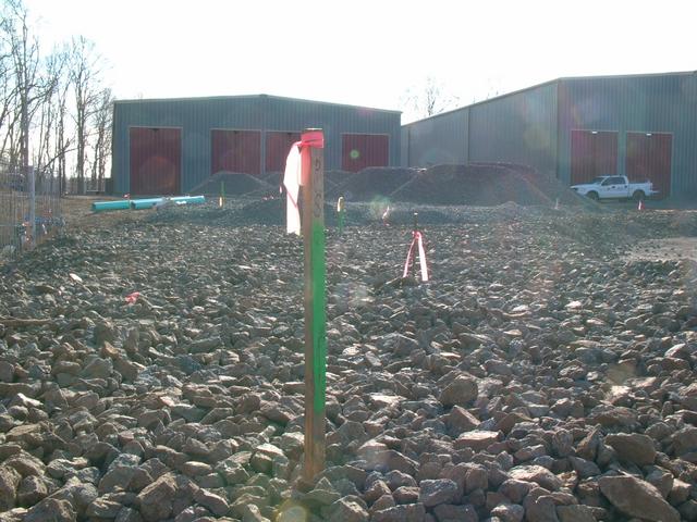
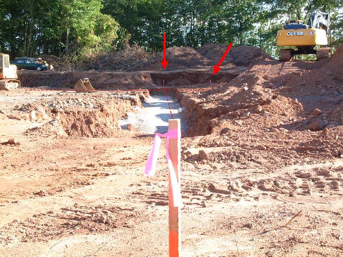
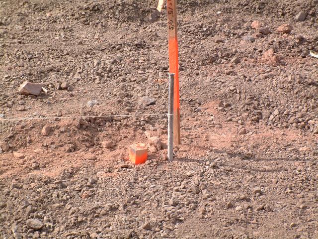
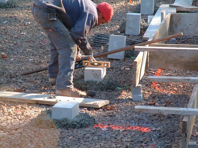
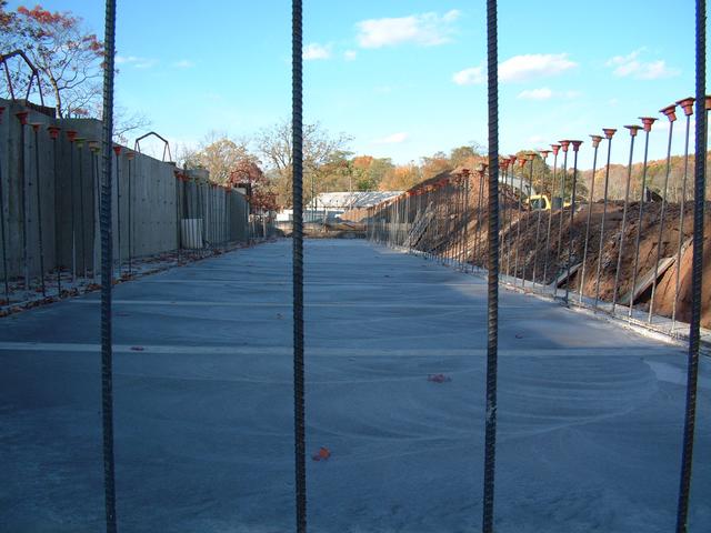
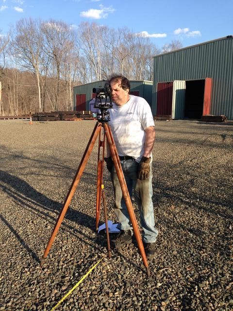
By the second week of September, the surveyor had re-staked the corners
of new building #1. Since the actual corners will be excavated for
the foundations, the stakes are set on an offet of 15 feet, where they
will not be disturbed. The image below has been augmented to highlight
the stake 200' away in line with the stake in the foreground, and another
stake which defines the perpendicular line. By stretching a string or
laser between stake points, the actual building lines can be followed
on the ground. The survey is accurate to 1/8 inch. A second stake,
set a few inches from the first, bears a nail head which marks the exact
control point.
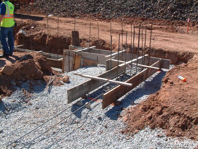
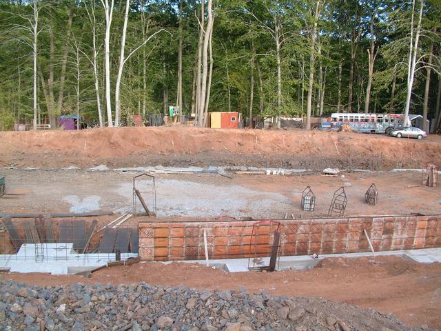
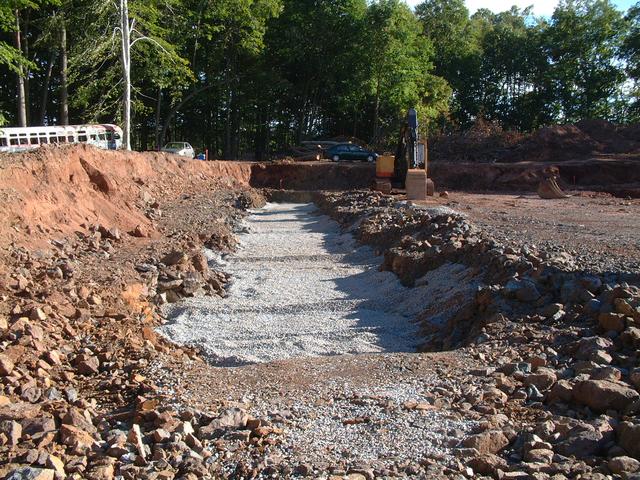
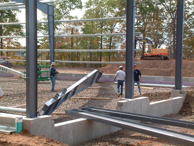
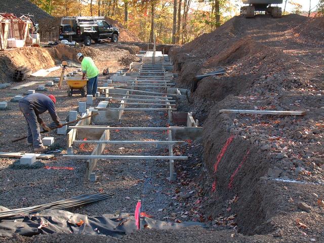
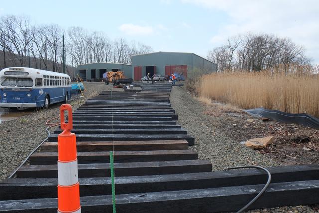
Let's take a walk around the perimeter of new building #1.
The previous view is taken from the northwest corner
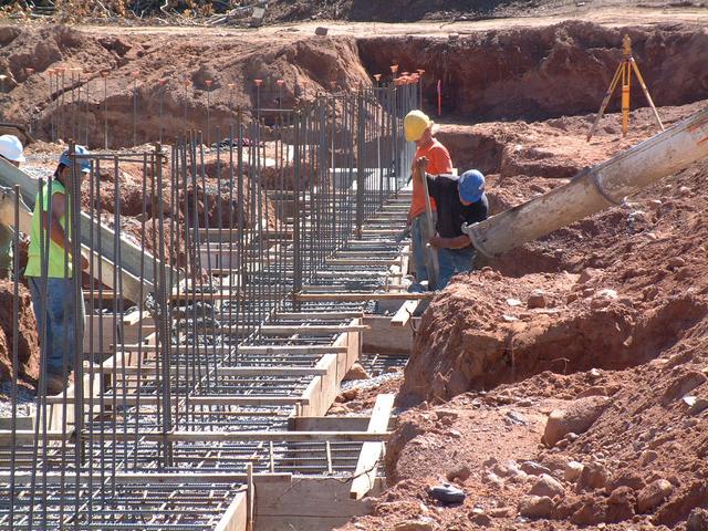
(geographic as opposed to railroad direction) looking south. View below
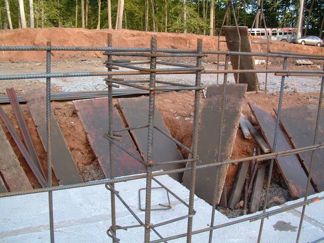
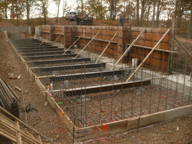
looking south from northeast corner. The trench is for the footings
which will support the columns, and smaller footings for the foundation/frost
wall. The trench has been excavated several feet below the surrounding grade
(which itself is about 3 feet below the final track/floor elevation) and
filled with crushed stone which has been compacted with a roller.
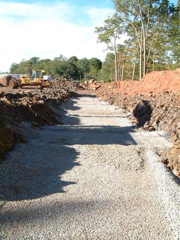
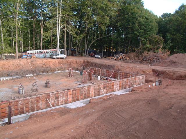
Southeast corner looking north (above) and west (below).
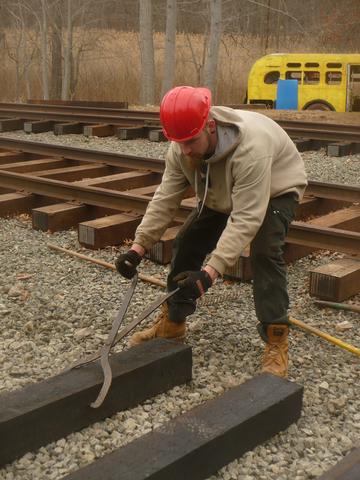
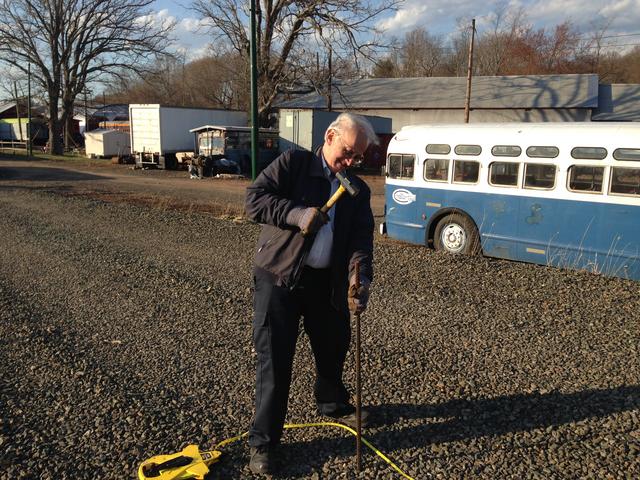
Southwest corner looking east. The old bus is part of the Haunted Isle set.
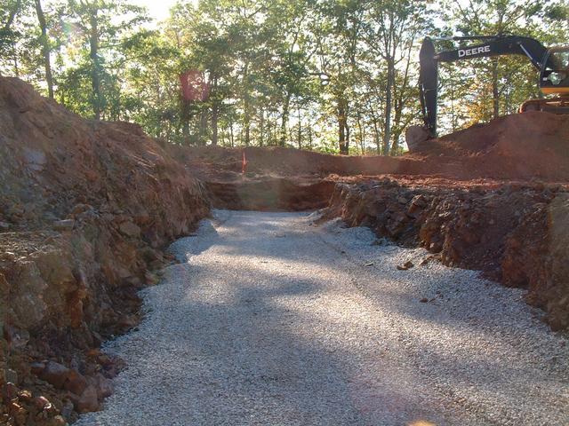
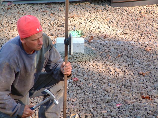
These white painted stakes mark the column lines for the structural
steel frames that support the building. There are seven such frames in
each building, including the front and rear walls.
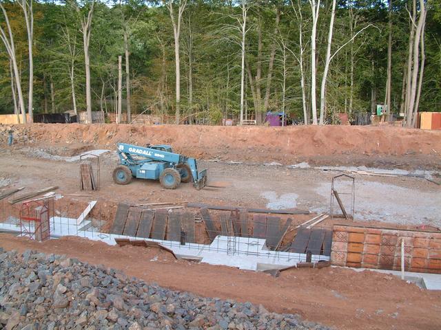
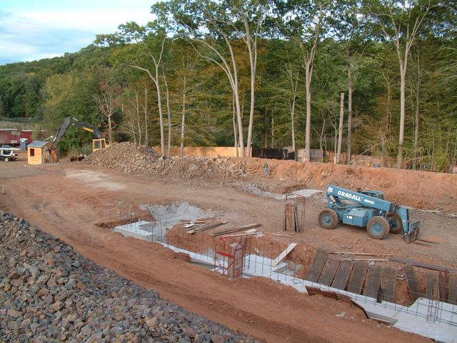
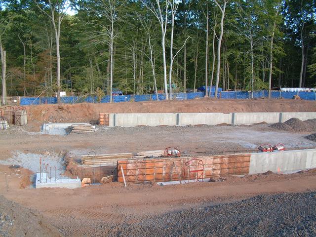
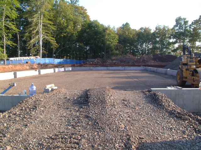
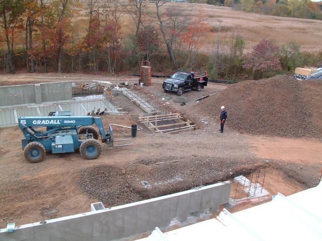
From the stone pile currently occupying the footprint of new building #2,
we can take in the panorama of building #1 from rear to front. When this
photo was taken, foundation excavation was still in progress near the front
of the building.
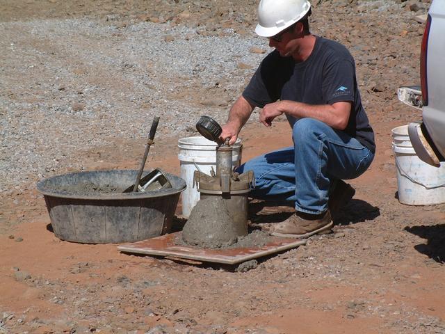
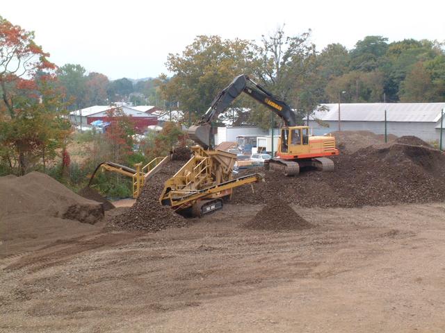
Screening Concludes, First Foundation Completed
Sep 27, 2013
: This screener machine was used to process the raw crushed rock, which is
loaded into the top of the machine. The stone falls over two heavy wire
mesh screens which are constantly shaking. The largest stones (over about
2") fail to fall through the screens and slide down the back chute. Stones
between about 1.25" and 2" fall through the top screen and are caught by
the lower screen, and exit the conveyor on the right. The remaining material
consists of fine stone fragments, dust and soil, and exits the conveyor
on the left. These materials are then stockpiled.
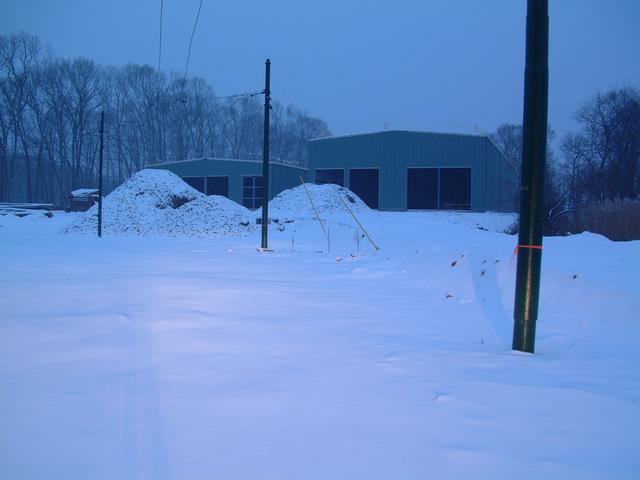
About a week later, screening operations are concluding. The large crushed
stone mountain is nearly gone. Much of the unscreened crushed rock has been
used up in general filling operations in and around the buildings. The
area where Building 2 will stand has now been brought up to rough grade,
about 3-4 feet below finished floor grade. Several large stockpiles of
the screened stone can be seen, including about 1000 yards of track ballast
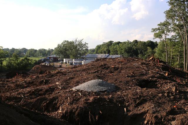
piled behind E.H. Blossom Barn. The cone and stake mark the center point of
the new Edwin Burch IV Memorial Loop.
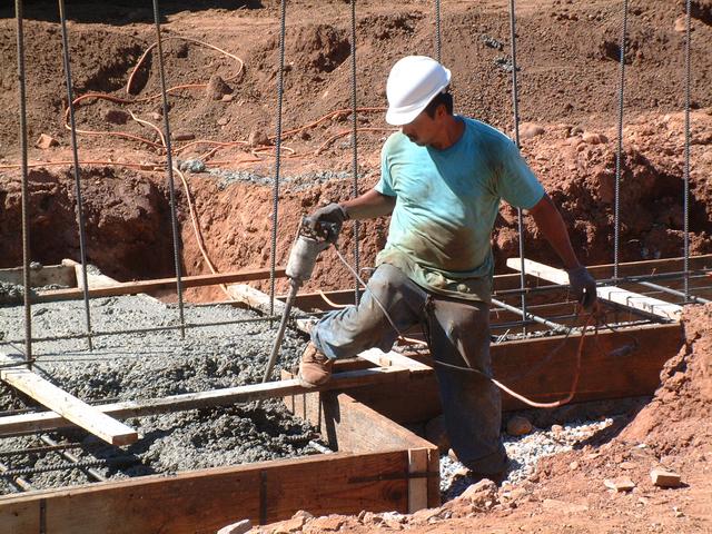
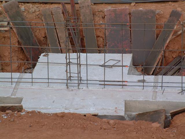
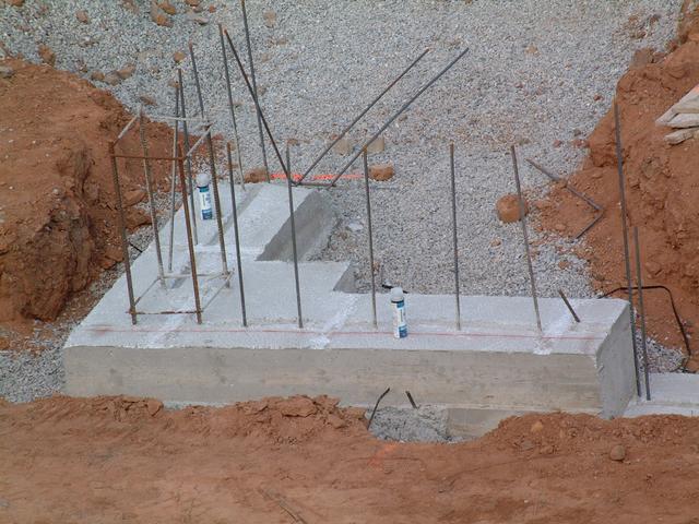
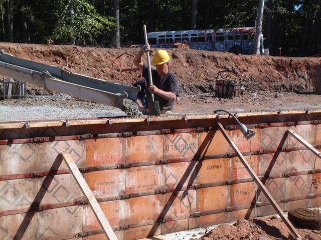
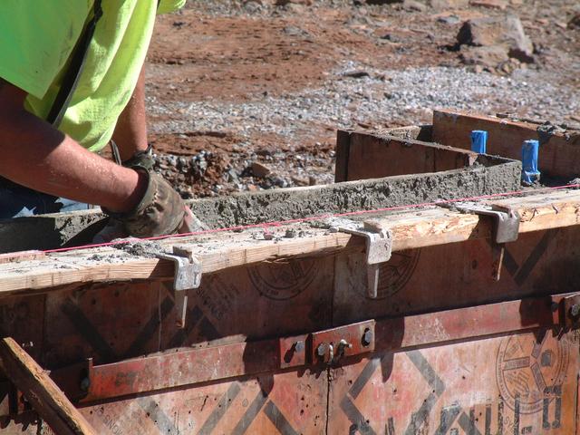
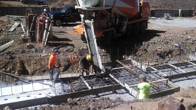
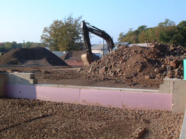
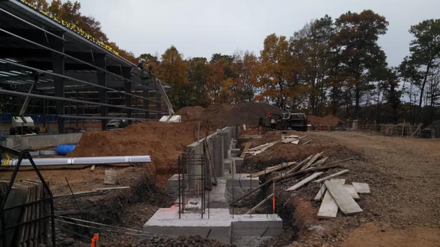
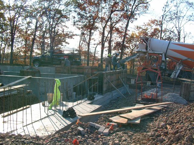
Around October 1, just the front walls and last side bays remained on the foundation pour.
These protrusions left behind from the form dowels will be invisible far below grade, and they'll help retain the foundation insulation panels during backfilling. Note the egress doorway midway along the east wall of building 1.
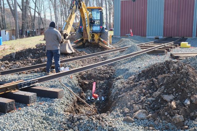
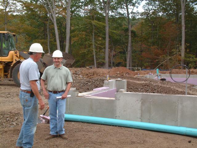
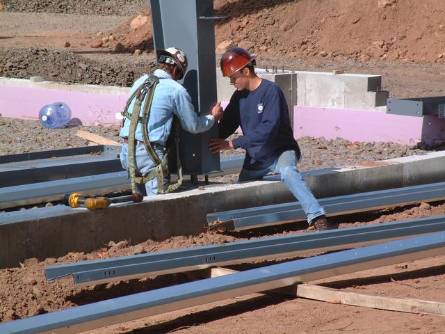
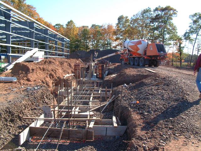
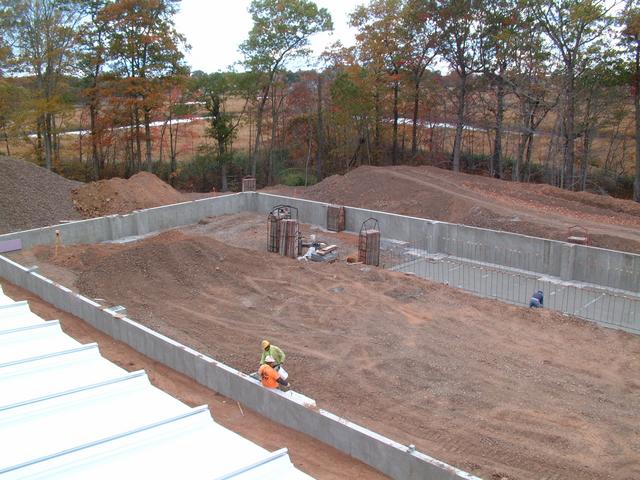
October 4, 2013: foundation work is complete, the footings have been back-filled,
and filling is taking place inside the building perimeter. Here Sven (Munger
Construction Co. foreman) and Rob (Vice President of Pasqualini Construction,
the site work subcontractor), discuss the grading.
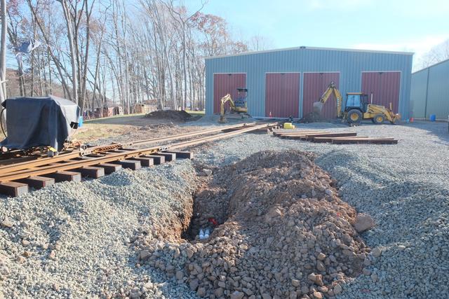
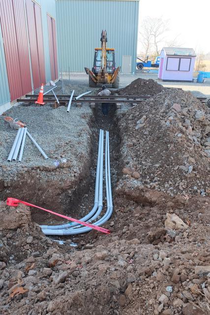
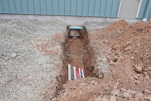
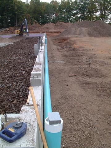
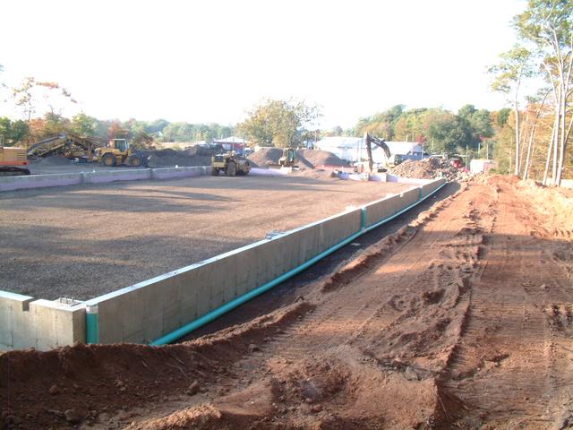
6" Schedule SDR-35 drain piping will pick up the discharge of the roof
gutters and downspouts, and convey the water to another pipe across the
south end of the project which will lead into the storm water retention
basin.
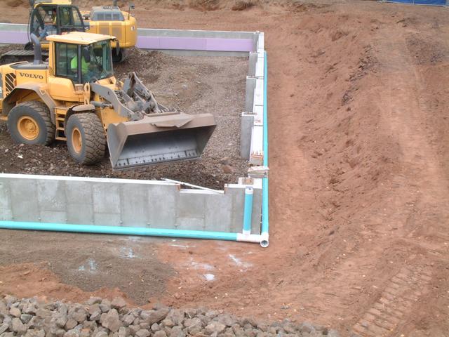
This temporary ramp is on the future alignment of track 83, and allows
construction vehicles to get inside the foundation wall perimeter.
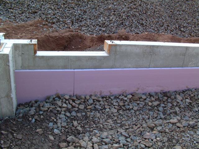
Egress door in the southwest corner of building 1 (aka building 8).
The foundation wall forms a curb 6" above the finished floor elevation.
Thus the doorway drops down. Note the foundation wall frost insulation.
From the topsoil pile behind the building looking north, showing the entire
complete foundation.
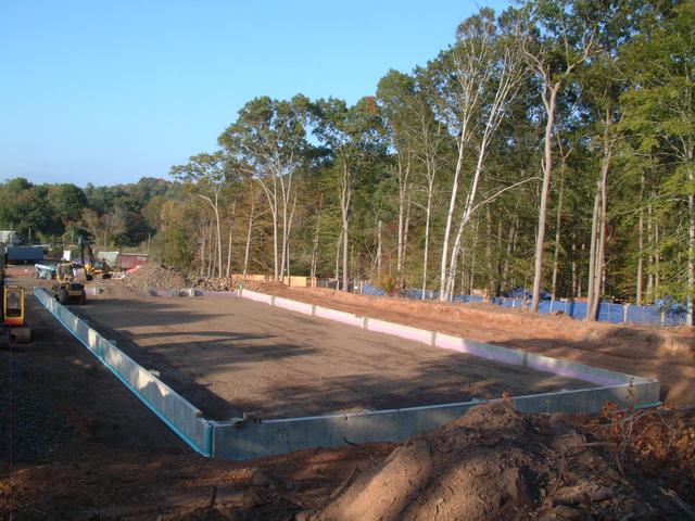
Looking north along the east wall.
This is the future doorway for track 81. Note the double step down: first a drop of
6" from curb height to floor height for the door jambs, which are 4"
heavy C-channels. Then a second drop to 6" below floor height to allow
for the rails. Once the track has been installed, aligned and leveled,
the concrete floor slab will fill in this large area and embed the rails.
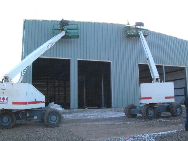
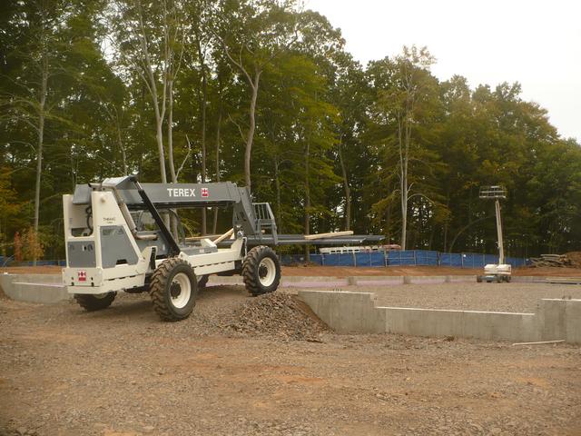
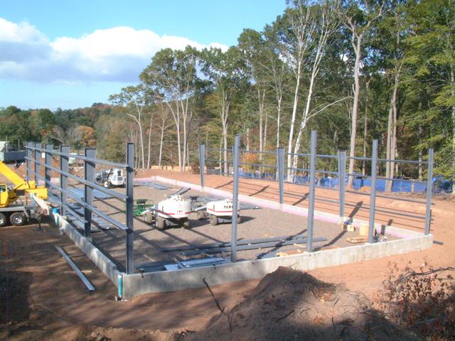
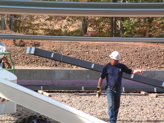
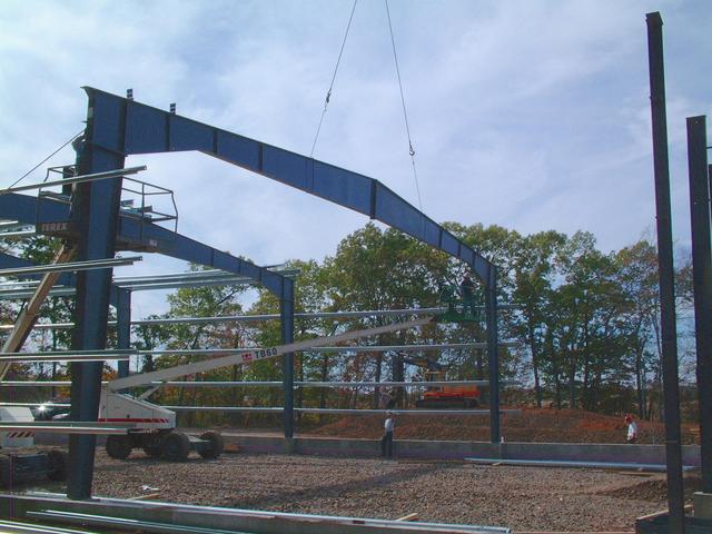
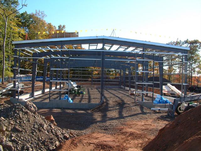
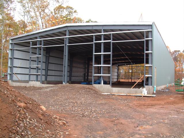
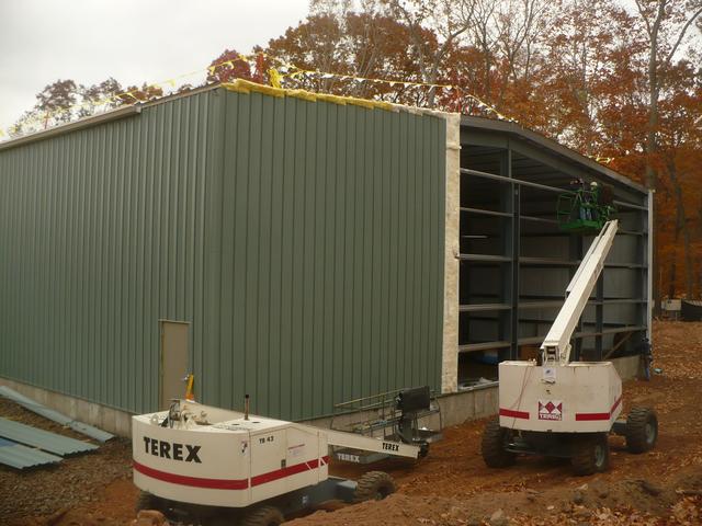
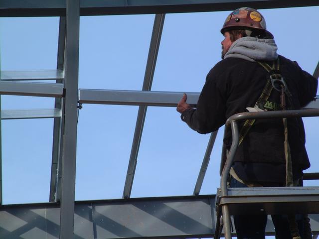
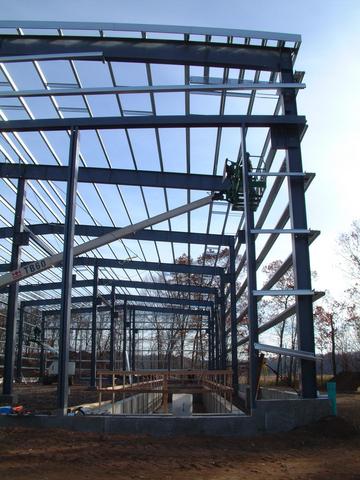
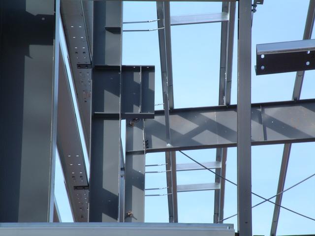
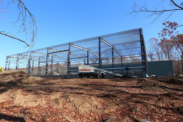
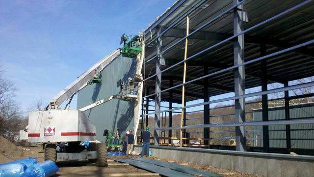
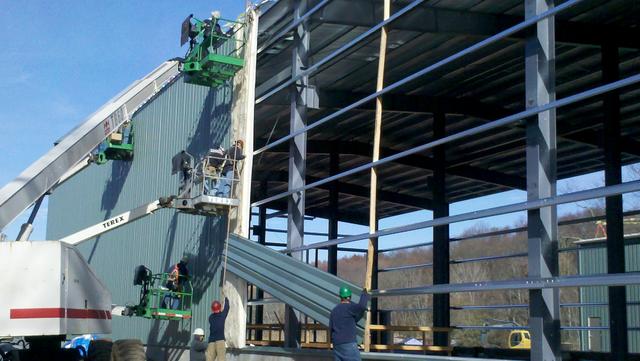
Building 1 Steel Is Up!
Oct 14, 2013:
In just a few working days, the steel superstructure of building 1 has been
erected! On Oct 10, First Choice Builders (the iron work subcontractor)
mobilized and moved the building components inside of the foundation
perimeter.
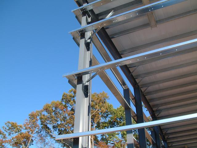
By Oct 11, the first 6 column lines are up (starting from the back of the
building) and some wall girts have been installed to stabilize the structure.
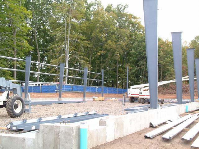
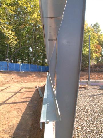
These are the Z-shaped wall girts which are bolted to clips on each column.
Each girt overlaps the other by a few feet at the joint. The wall sheets
will be screwed to the outside face of the girts.
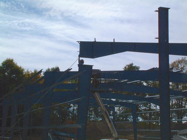
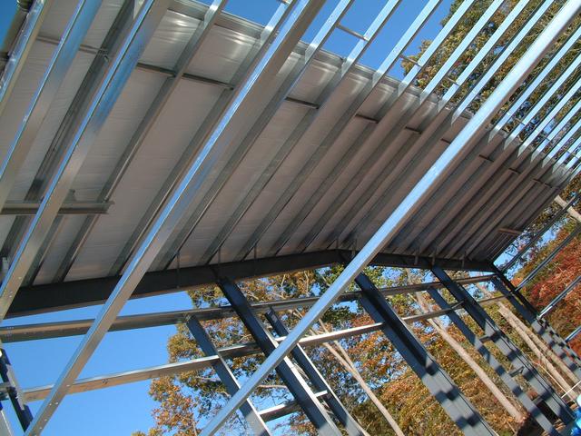
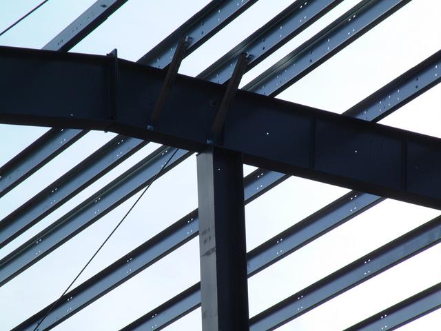
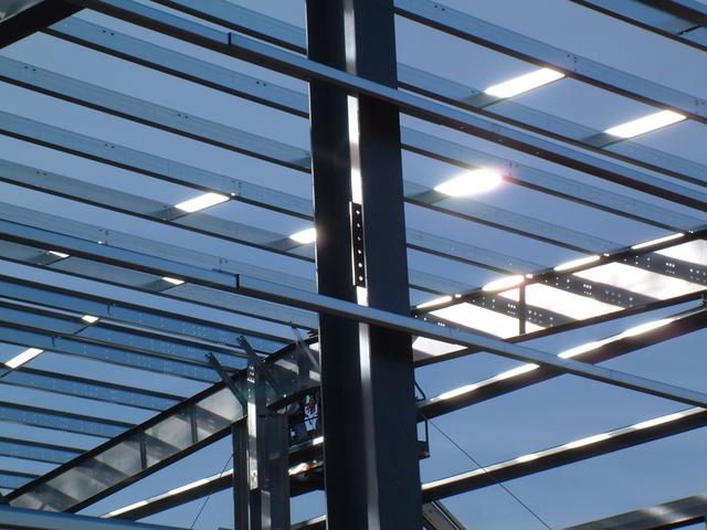
Oct 14, 2013:
Looking skyward from the back of the building, lines 7,6,5,4 and 3 have
been completed with roof beams assembled to the columns.
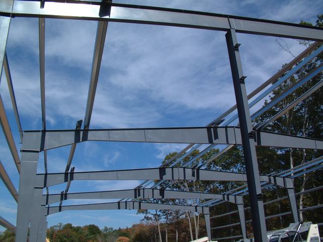
Each frame consisting of the two columns and the roof beam is considered
a "rigid frame" which is capable of resisting being distorted into a
parallelogram by crosswide wind forces. However the structure requires
bracing to resist forces acting along the length of the building. That
is the function of this X-brace inside the wall, and similar bracing which
will soon be installed in the roof bays. The threaded brace rods are held
in tension by nuts and a special curved washer.
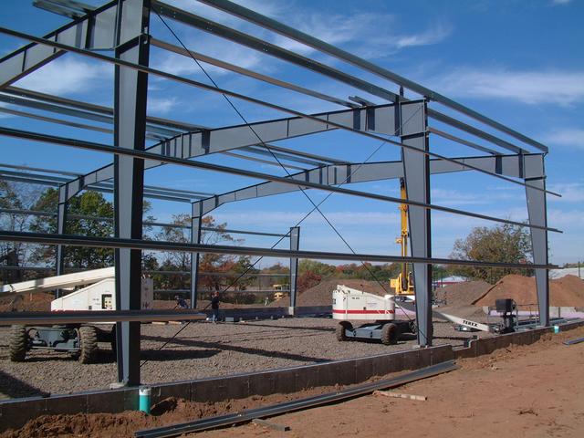
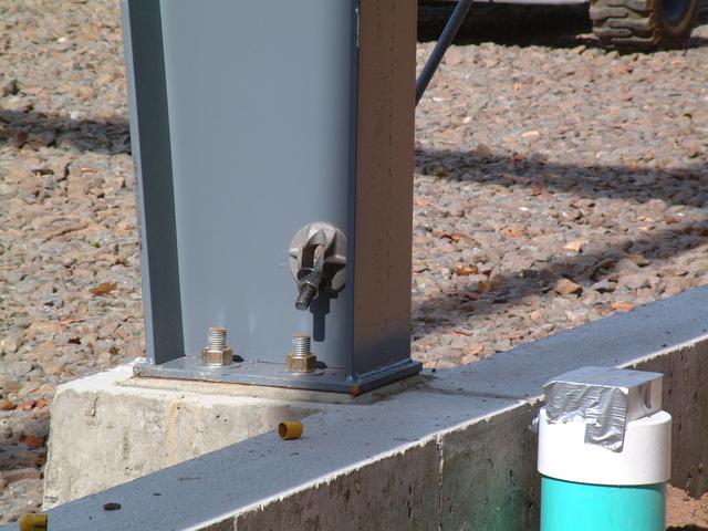
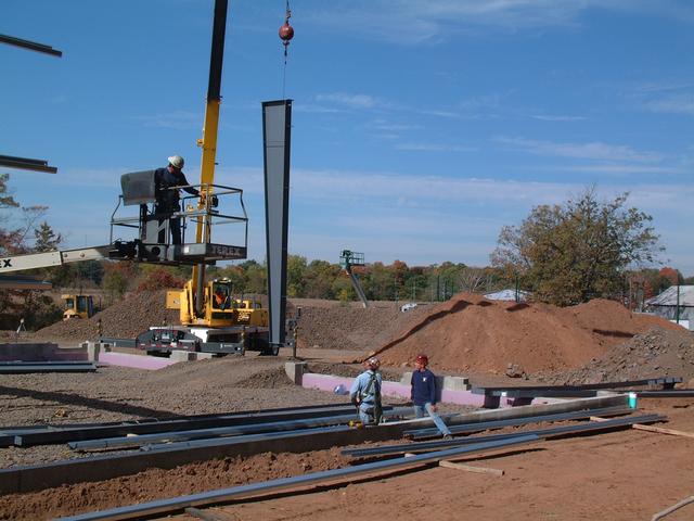
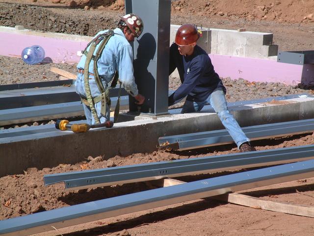
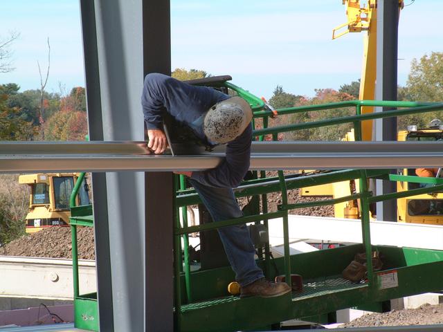
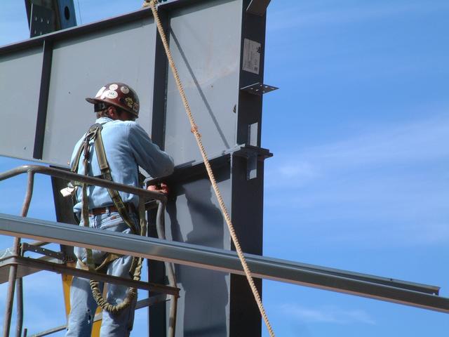
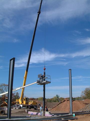
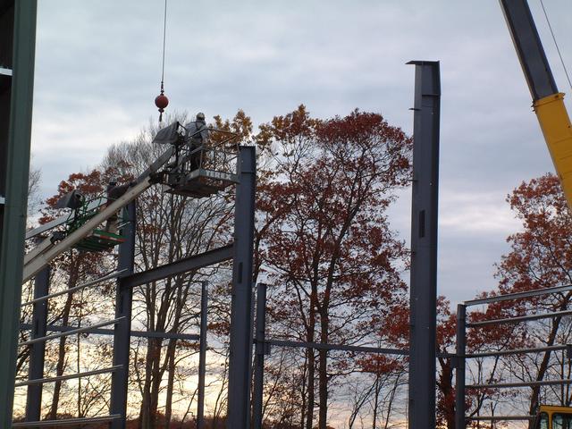
Setting columns on frame line 2. The column is picked up by a crane and
dropped on the anchor bolt plate.
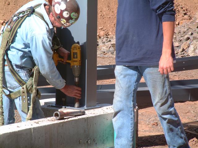
Construction workers guide the column into place and line up the holes in
the bottom plate with the 4 anchor bolts, then bolt it down with an
electric impact wrench.
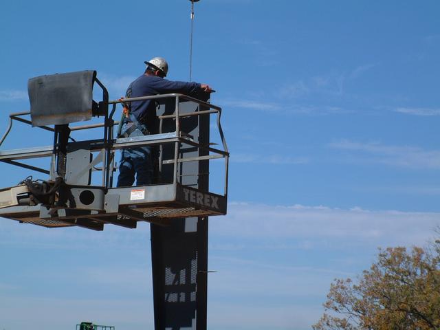
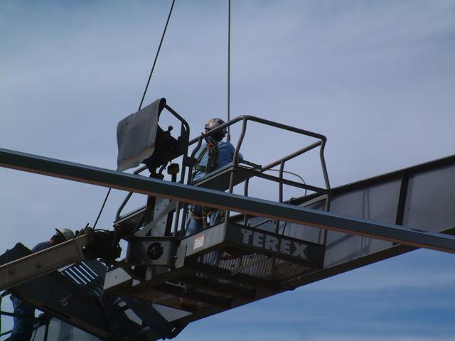
A worker in the aerial lift then disconnects the sling from the top of the column.
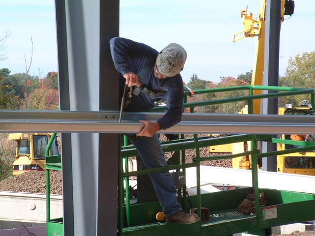
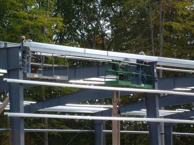
As columns are set, girts are lifted and set on the column brackets.
The construction worker
uses a "spud wrench" with a tapered end to line up the holes, then puts in
one temporary bolt to hold it in place.
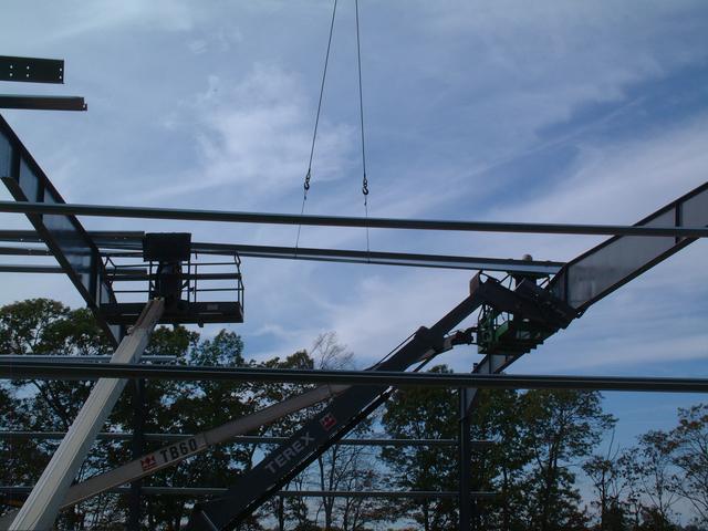
Each building is 70' wide. A single roof beam of this size would be too
long to ship without an expensive oversize permit, so the beam is made
of two pieces which are bolted together on the ground. Then the assembled
beam is craned into position.
A worker on the ground with a "tag line" helps to stabilize the load as
it is guided on top of the columns.
This telescoping forklift was used to prop up the beam until it could be
completely bolted down.
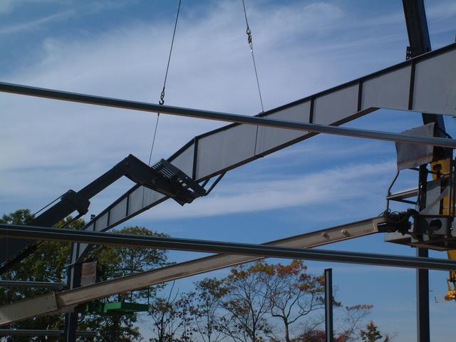
The aerial lifts are repositioned to remove the crane slings.
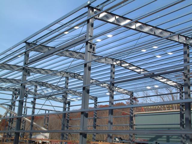
Next some roof purlins are placed and temporarily bolted down. These will
ultimately hold up the roof, and for now will stabilize the structure in
lieu of the diaphragm action that the roof and wall sheets will provide.
The eave purlins are C-shaped instead of Z-shaped
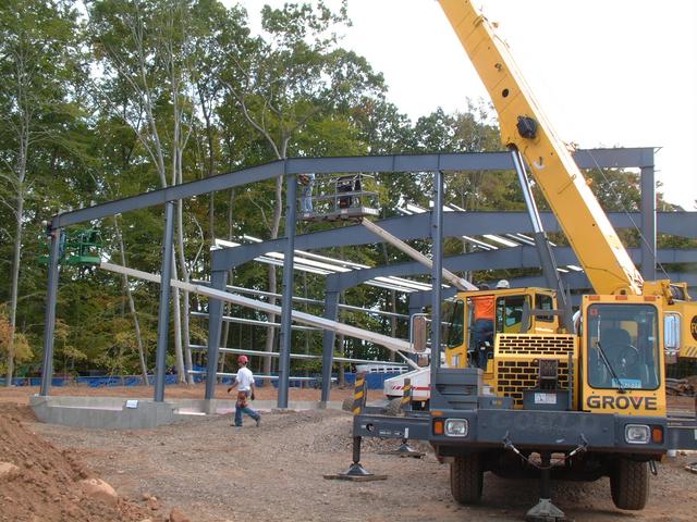
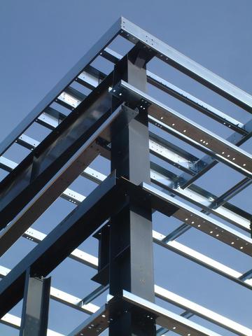
Frame lines 1 and 7 are the end walls and are of different construction.
They bear only half (approximately) of the load compared to the side
columns, and since they are end walls, additional columns can be used which
will not interfere with the open floor plan. Therefore these columns
are considerably smaller. Here one of the columns of the front wall is
set down.
The last roof beam is placed on the front wall.

And building 1 superstructure is complete!
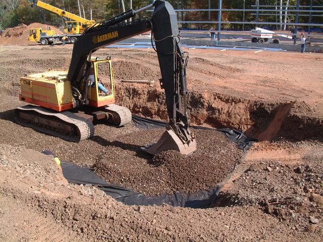
Meanwhile, Building 2 Foundation Work Begins
Oct 11, 2013:
The excavation begins for the west side of building 2. The new pit track
is on this side, and the footings for the wall will overlap the pit floor
slab. Therefore both are being done at the same time. The orange stake
in the foreground represents the west building line, and we are looking south
towards the back of the building. The pit is 100 feet long.
This stake has been set by LWF surveying as a grading control. The crosshair
near the bottom represents elevation 14.0 (NGVD 1929 datum). The tracks and
finished floor of both new buildings will be set at 14.2
 Oct 14, 2013:
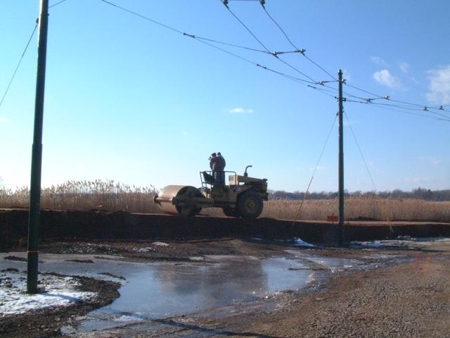
 3/4" crushed stone that was made on-site is spread on
top of a geotextile fabric.
A portable compactor is used where the steamroller can not reach.
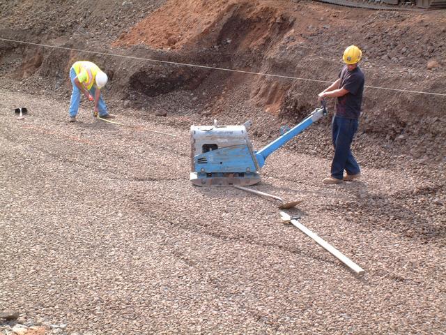
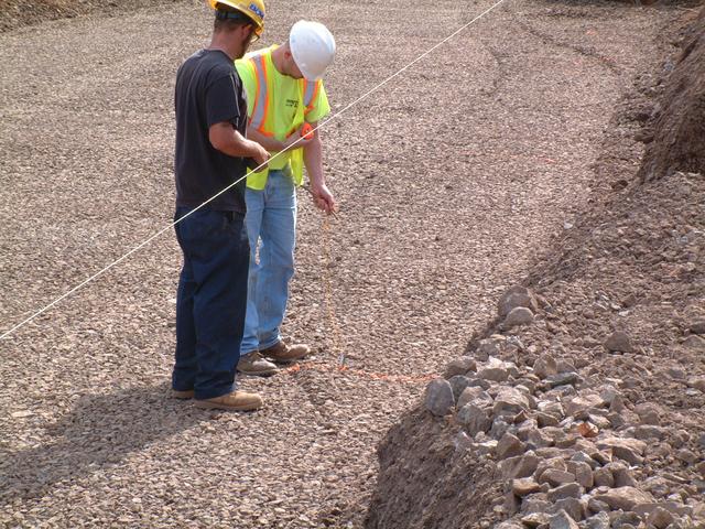
A string line is stretched over the control point that marks the west
building line of building 2. From the taut string, a plumb-bob is dropped
to transfer the line to the bottom of the excavation.
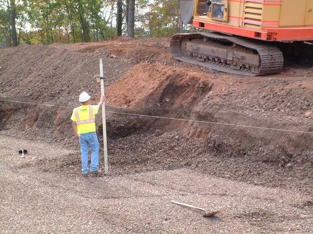
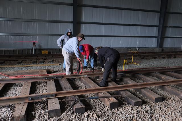
Rob from Pasqualini Construction uses a grade rod with a laser detector
to find the laser reference line established by the rotary laser (not
visible in photo). He is then able to tell exactly how far down the bottom
of the footing must be by subtracting the computed number of feet and
inches from the reference line.
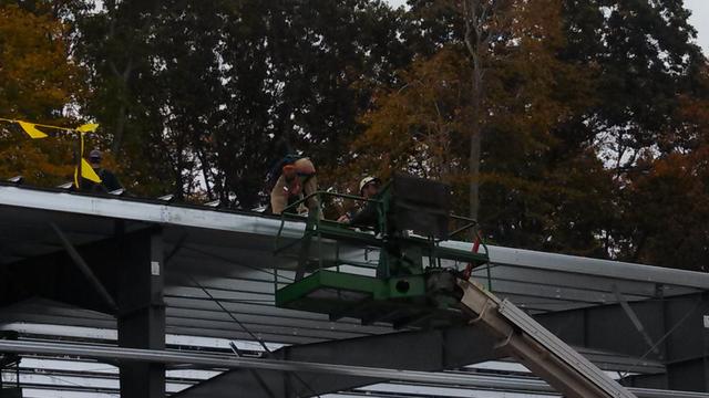
Building 1 Roof Completed
Oct 21, 2013:
Installation of roof sheets began on the north end of building 1.
Bracing struts where the end and side walls meet.
By Oct 23, the roof is 75% done. Workers use this platform lift
to safely access the roof structure.
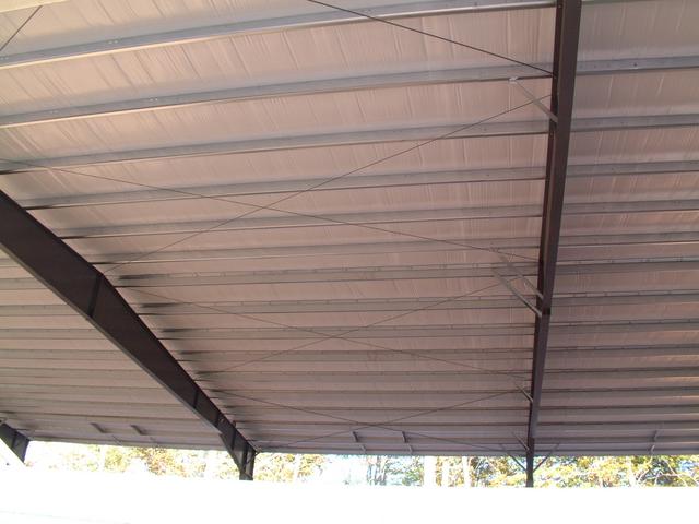
X-braces in one of the roof bays along with those in the wall bay provide
the required longitudinal stiffness.
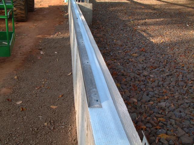
Angles have been applied to the foundation wall. These will support
the bottom of the wall sheets. Note the thin layer of foam insulation
to provide a "thermal break".
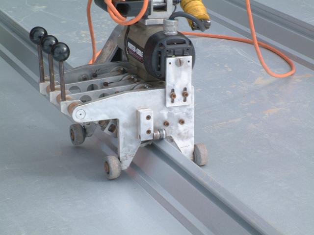
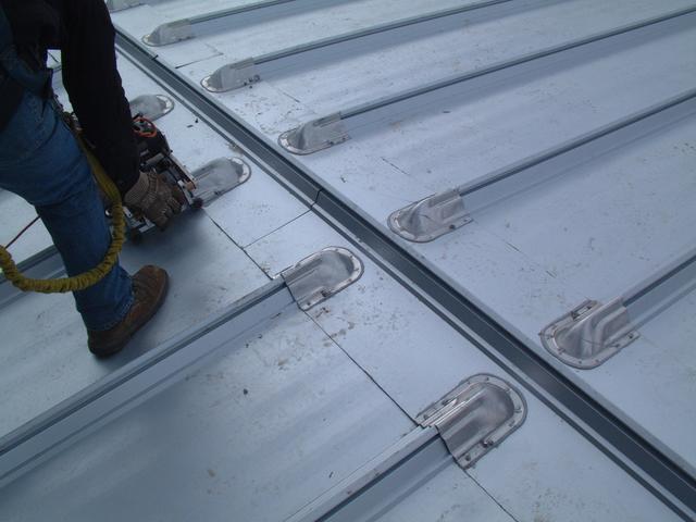
By Oct 25, all roof sheets have been installed. The joints between the
sheets are made using a "standing seam" which eliminates any penetrations
of the roof membrane by fasteners. The sheets are clenched around protruding
clips which are anchored to the purlins. A special crimping machine then
crimps the edges of the sheets around the clips. There is also a seal
inside the crimped joint.
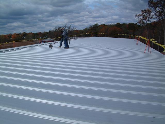
A special ridge cap completes the top of the roof
View from the north end (railroad west) of building 1.
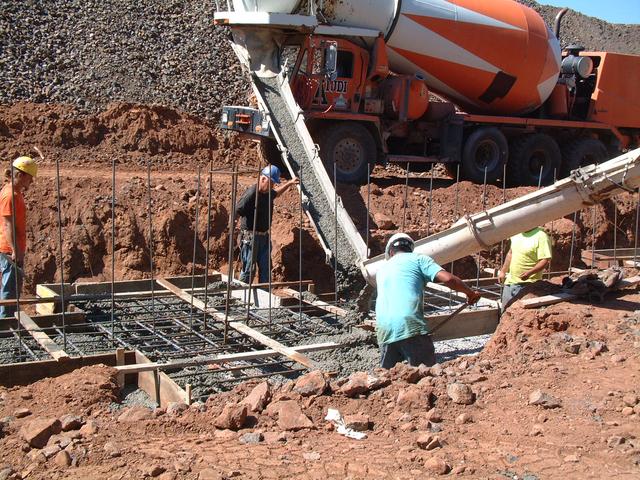
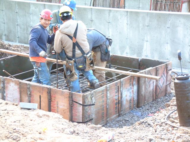
Building 2 Foundation and Pit Slab Poured
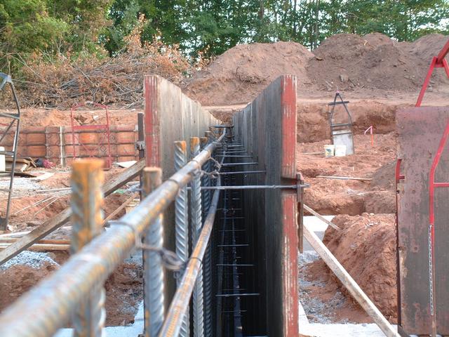
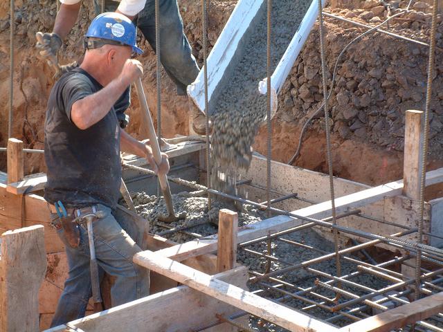
Footings and walls have been completed for all of building 2 except the front
wall and the interior columns. Here we see a section of the east wall formed up. Concrete has just
been poured and is being finished. A few days later, the forms have been
stripped.
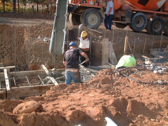
A little further along the same wall, footings are poured on Oct 21:
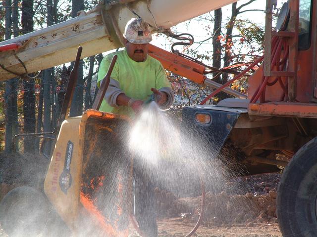
One of the concrete workers washes off the tools.
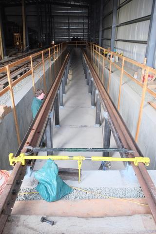
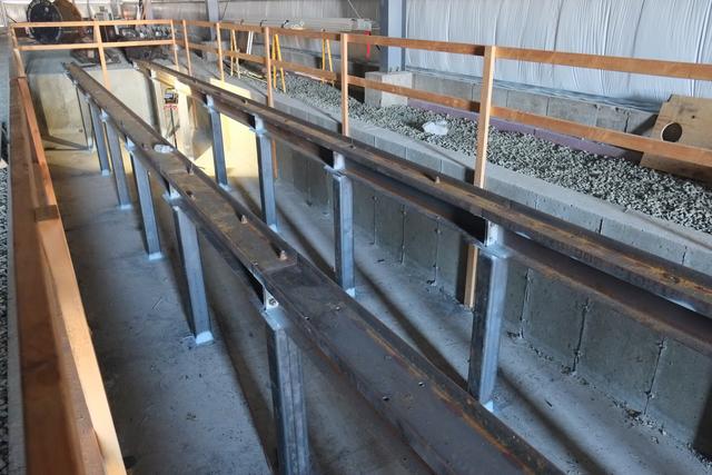
Building 2 contains provisions for a future maintenance pit. A series
of 8" I-beams embedded in the pit floor slab acts to control the gauge
and transfer the load into the slab. In the future, 6x6 structural steel
tube posts will be welded to these beams. During the slab pour, the beams
are supported on cement blocks which are carefully set to the same level
using a rotary laser.
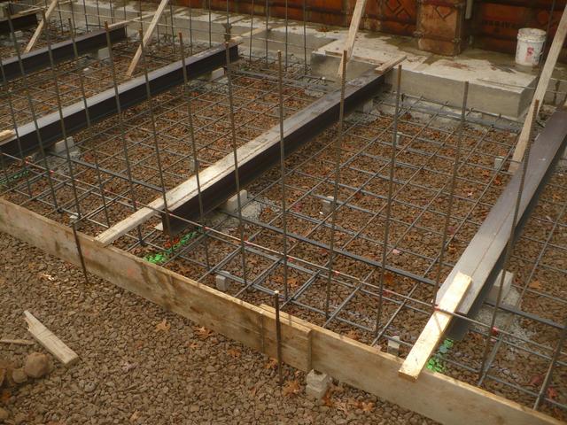
Oct 24: The pit floor beams are in place along with the rebar mat, and rebar
for the walls connected, all ready for pouring.
Oct 25: Standing on the floor of the future pit, and aerial views of
building 2 taken from the roof of building 1. The square holes at the
bottom of the east wall are for electrical conduits and future water
piping.
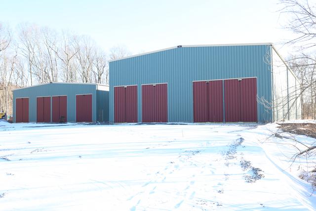
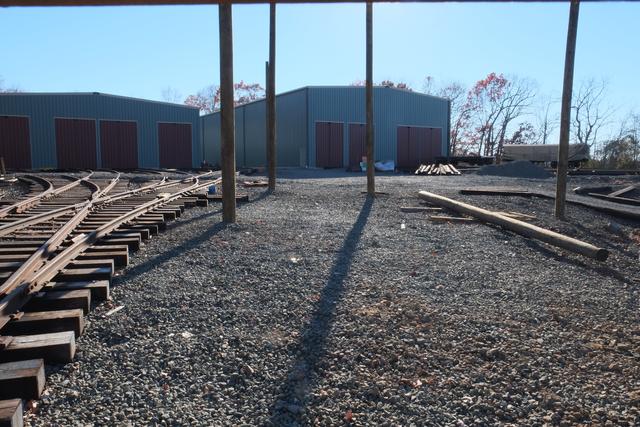
Building 2 foundations completed, Building 1 Siding completed
November 4, 2013:
The concrete workers were on the job last week, forming up the remaining walls,
and the footings and piers for the interior columns of Building 2. Concrete was poured at the end of the week, thus finishing foundation work.

The walls of the future rail car maintenance pit in Building 2 were also
finished during the week of Oct 28. We are standing outside the front of the
building looking at the doorway for track 4, with the pit beyond.
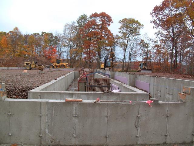
Taken from the topsoil pile behind the buildings, looking north (railroad
west) at building 2 foundation, with building 1 on the right.
From the back corner of building 2 looking towards the pit. The piers for
the interior columns are visible. Some backfilling of the building interior
has taken place.
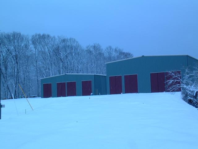
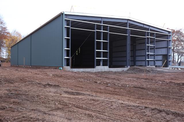
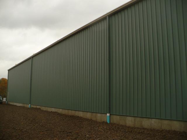
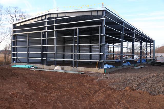
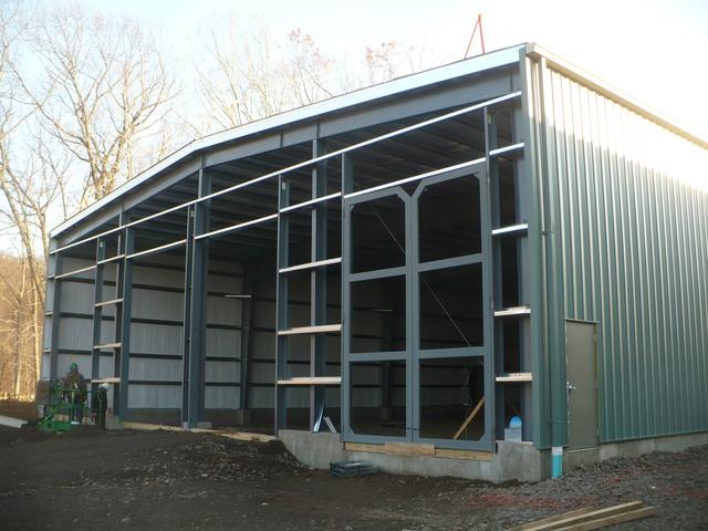
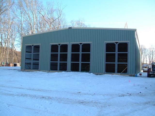
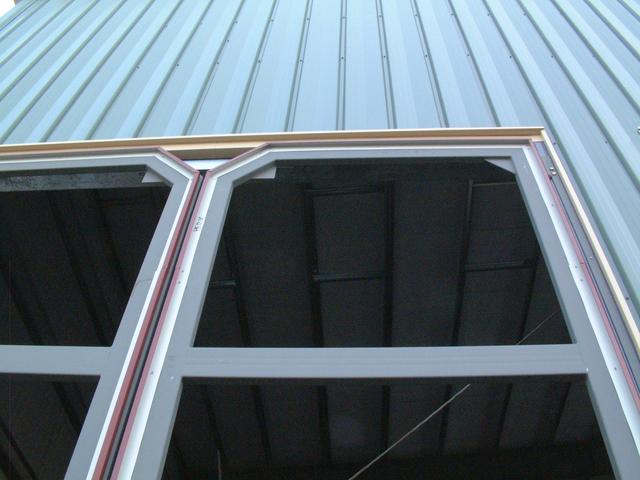
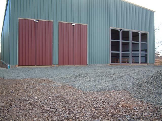
The skin of Building 1 is now complete, with the exception of the end walls.
Below is the front of the building. Note the framed openings for the four
12' wide x 16' high doorways.
The back wall of building 1. Note the same framed doorway openings as in
the front, but with girts across them. In the future should it be desired
to place doors in the back of either building, the framing is in place to
do so.
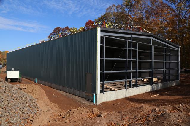
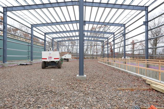
The east (railroad north) side of building 1.
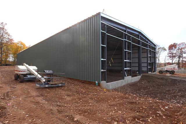
Wide angle view of the entire west side of building 1.
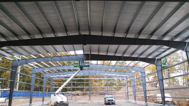
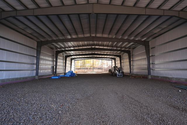
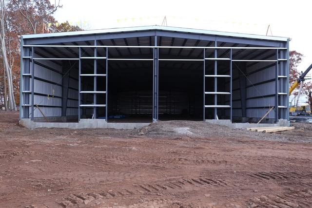
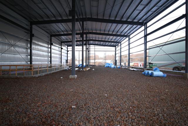
Interior of building 1 showing the 70' clear-span construction. Walls and roof
are insulated. Although this building will not be heated or air conditioned,
insulation will reduce temperature and humidity fluctuations.
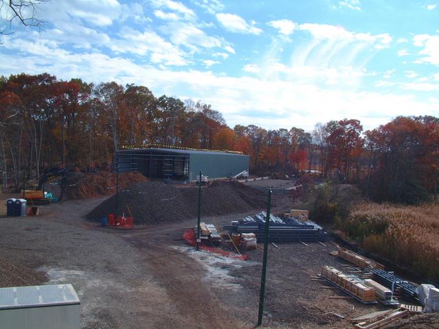
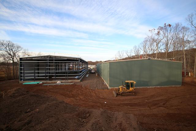
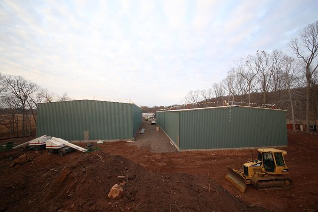
And finally an overview of the entire project taken from about 40' up
in the aerial lift.
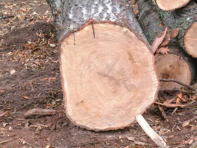
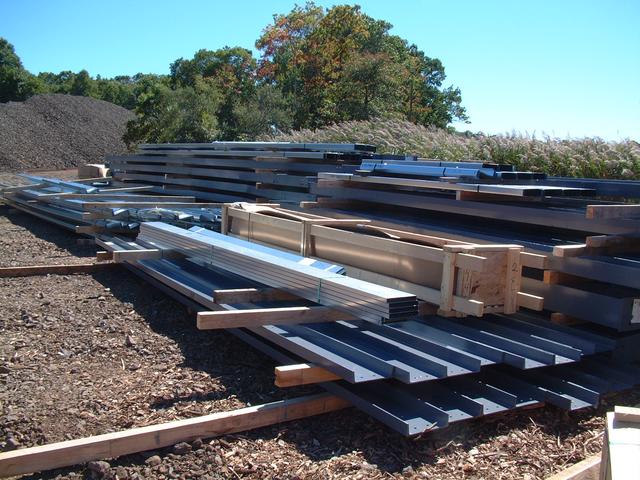
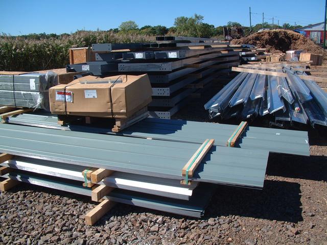
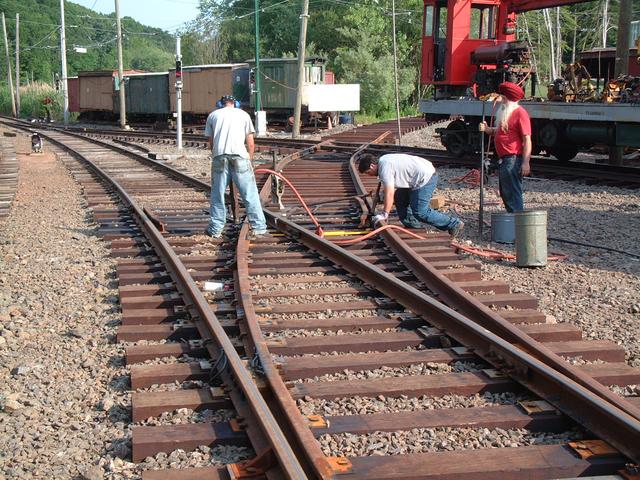
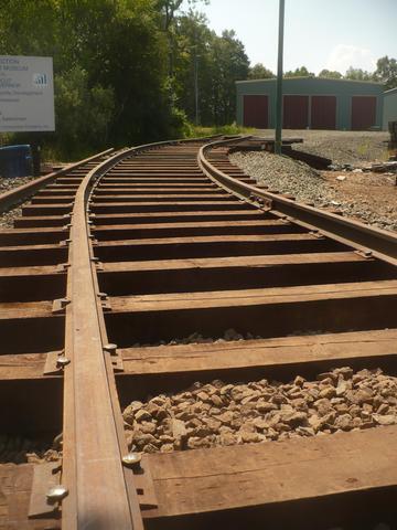
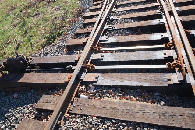
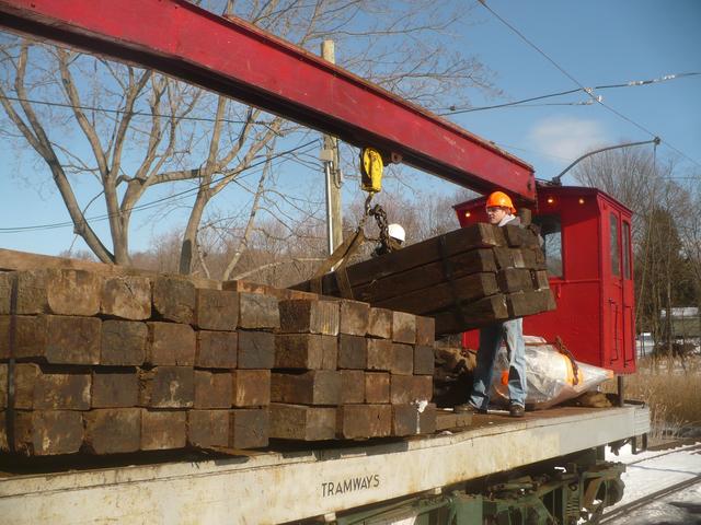
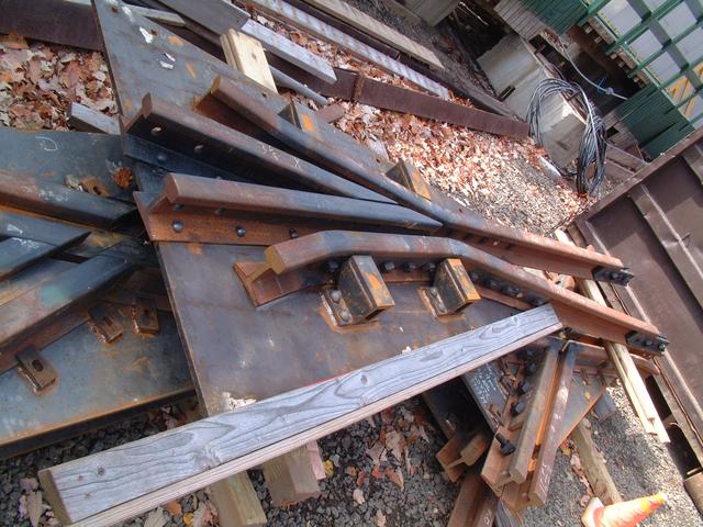
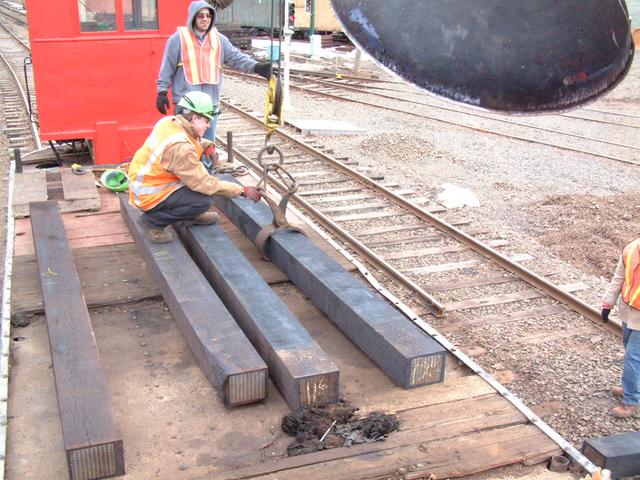
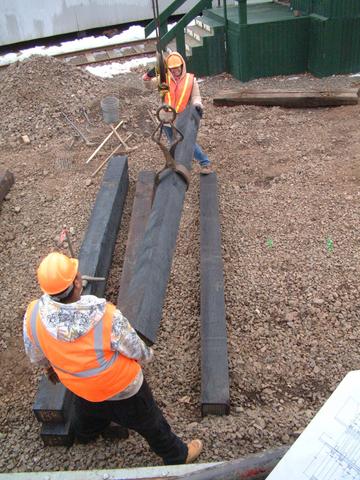
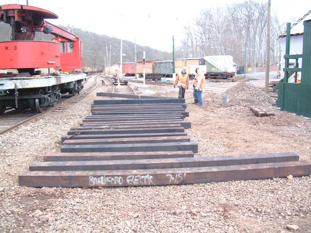
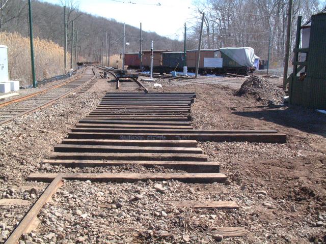
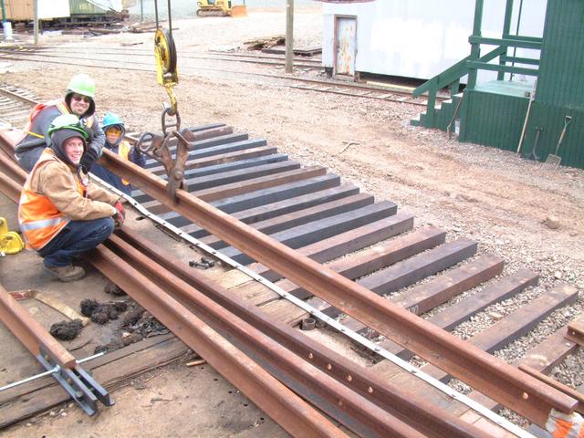
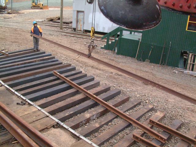
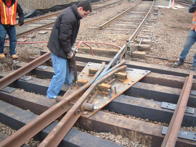
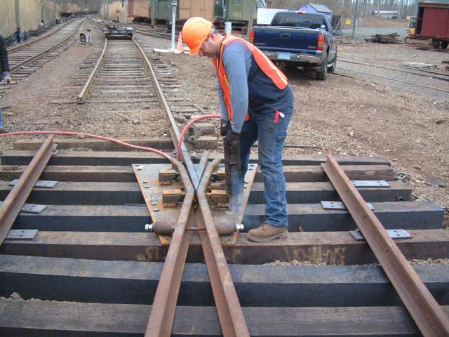
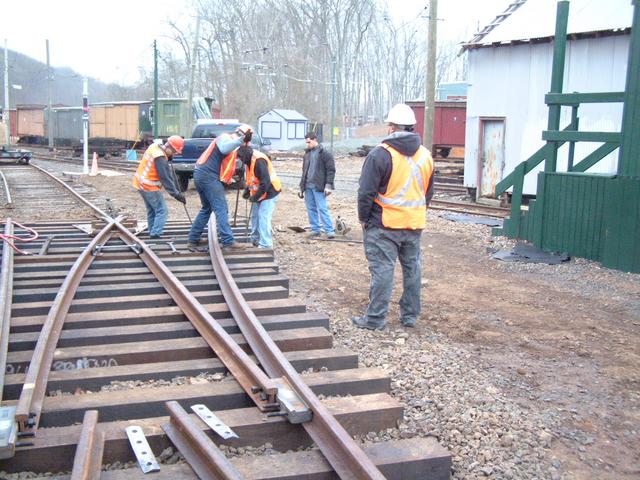
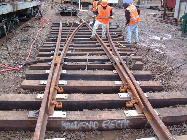
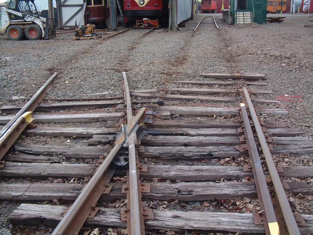
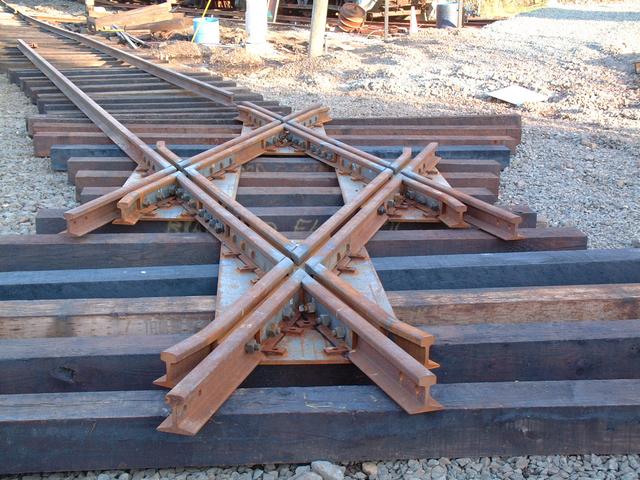
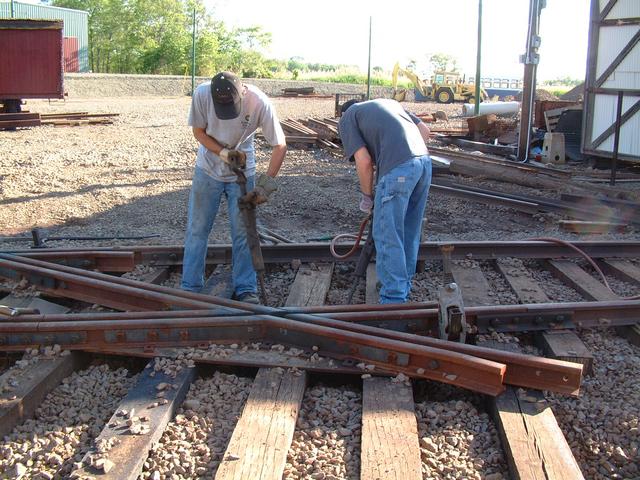
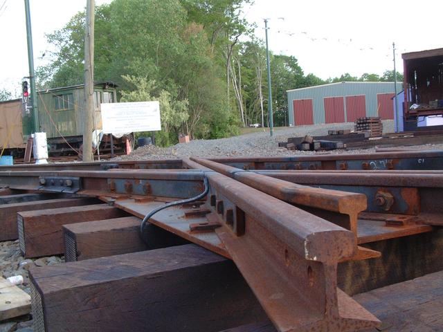
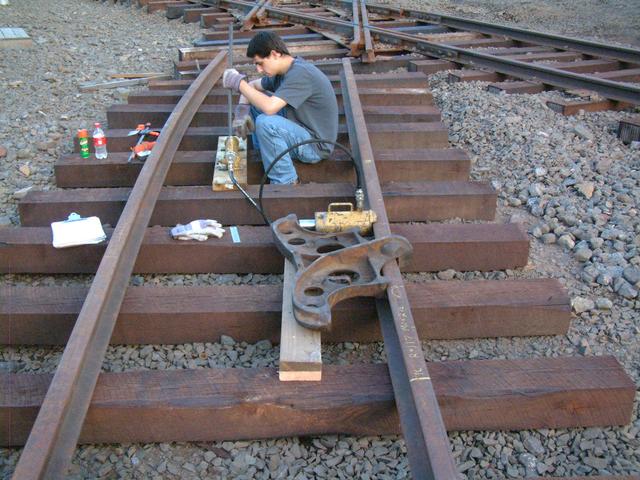
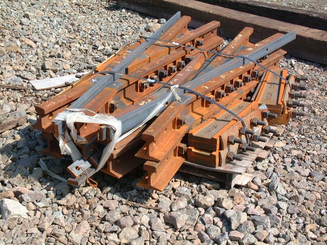
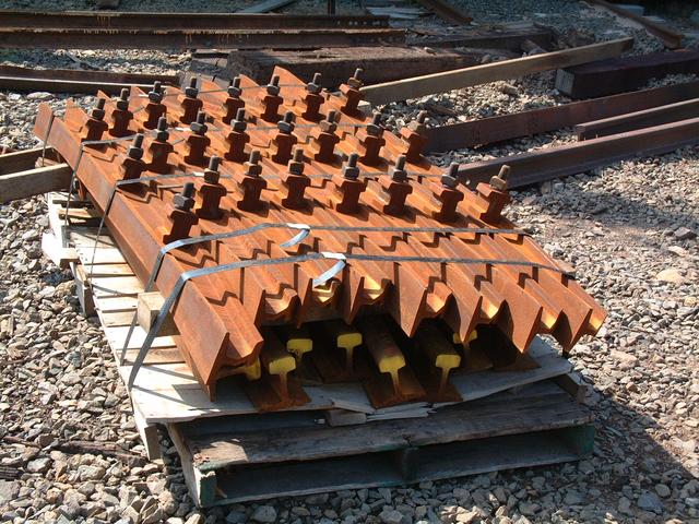
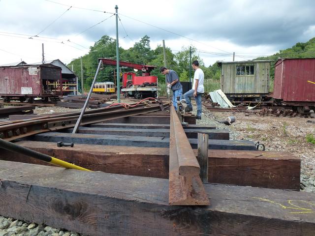
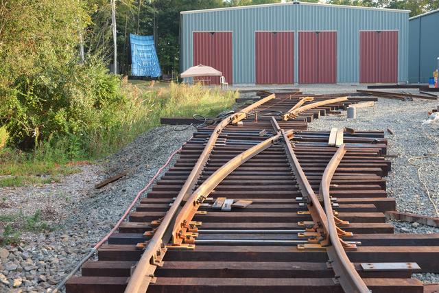
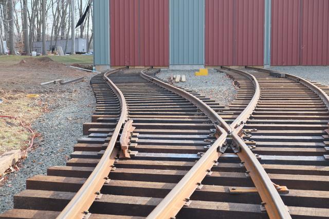
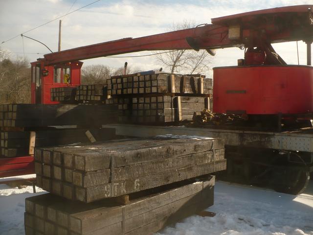
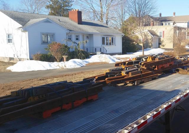
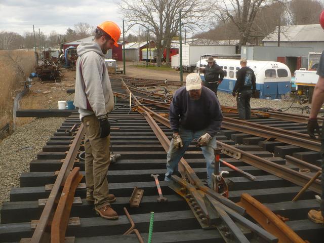
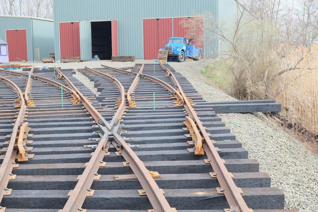
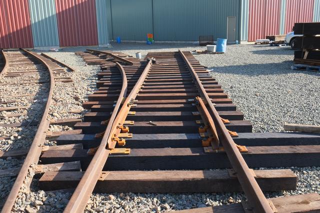
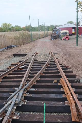
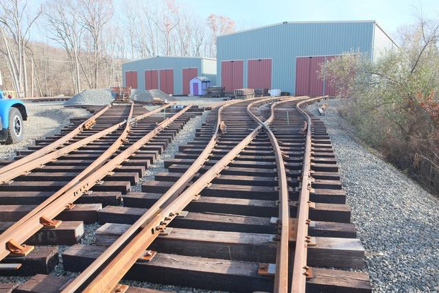
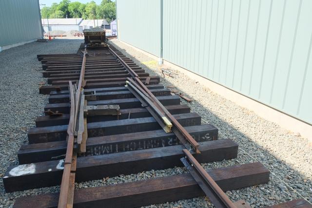
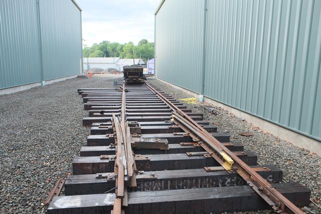
Track special work arrives
What will be the first new turnout to be installed at the museum in over 30
years has arrived from our supplier, Ohio Valley Trackwork. Below we see
the #4 double-spring frog which is part of the turnout from the mainline
track towards the island. Beneath it are parts of the 35 degree crossing
of Narragansett side track. The switch point rails, guard rails and other
small hardware were also part of this delivery. Work will begin to install
this specialwork during November and December. Your donations to the
Elevating the Collection campaign will ensure that we have the funding in
place to purchase and install the remaining 11 turnouts that are needed to
complete the new track plan and allow us to access all of the tracks of
both new buildings!
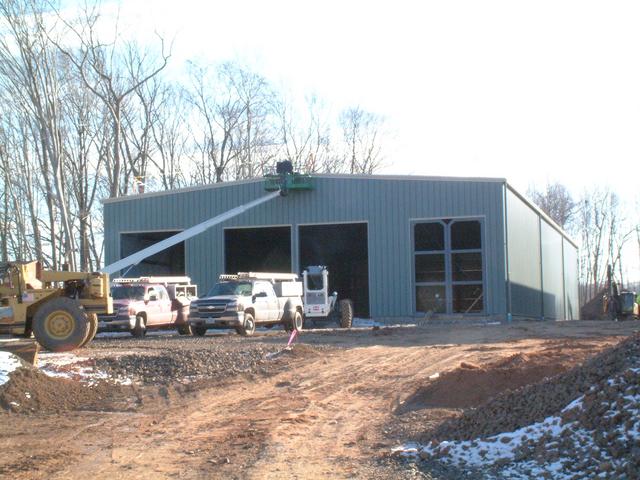
Building 1 approaches, gutters and trim
November 7-15, 2013:
Building 1 is complete with the exception of the doors, siding and trim of
the front wall, and interior finish grading. The approach ramps are
being rough-graded now.
These will contain the track "ladder" for building 1.
Roof gutters and downspouts being installed near the rear of building 1.
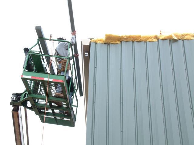
Installation of wall siding moved very rapidly, but we managed to catch one
photo of the process at the rear wall of building 1. Note the insulation
blanket. Although this building will not be heated, wall and roof insulation
will help control temperature and humidity fluctuations.
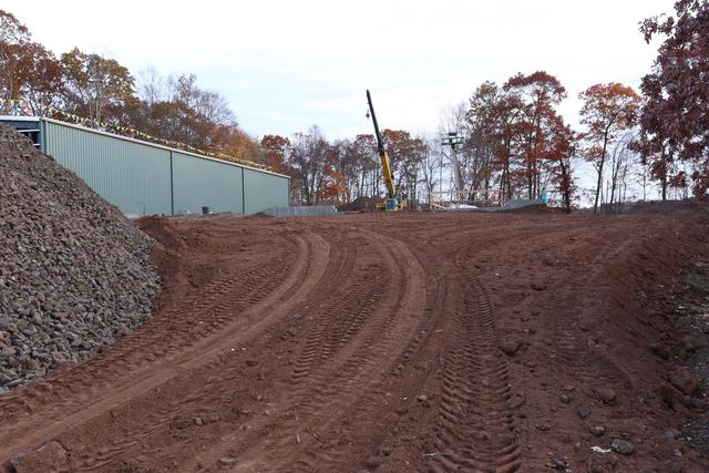
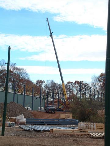
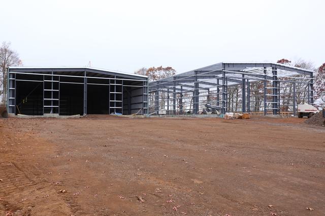
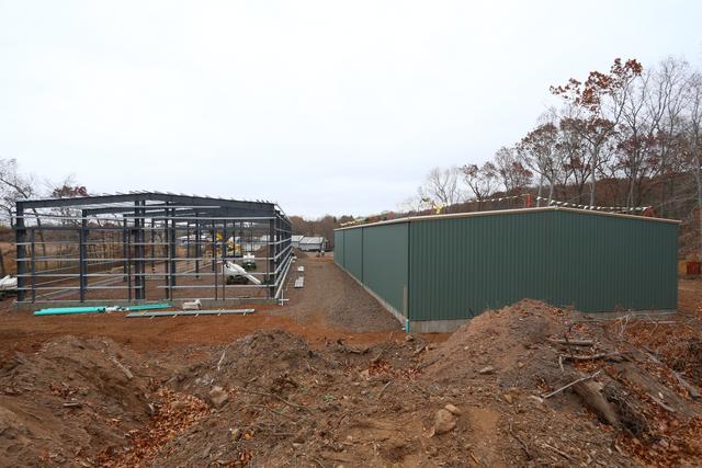
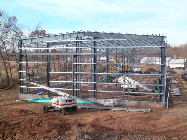
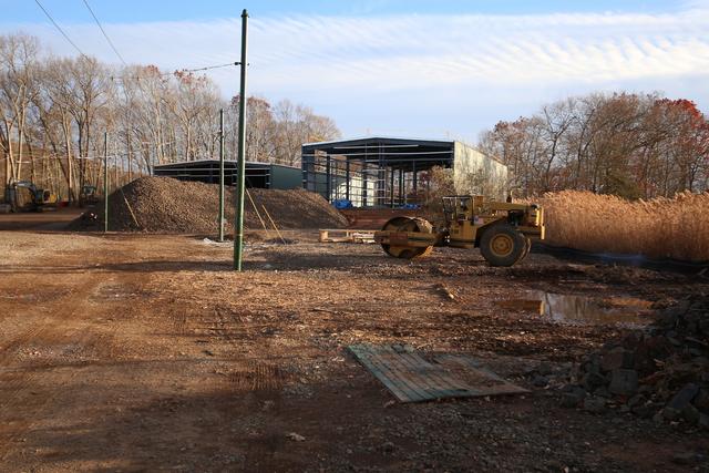
Building 2 steel frame completed
November 9, 2013:
Part of the approach ramp to building 2 has been rough-graded. Looking up
the ramp, the crane in the distance is staging the building columns.
View from the rear of the site.
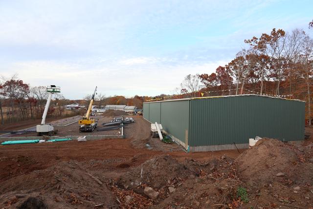
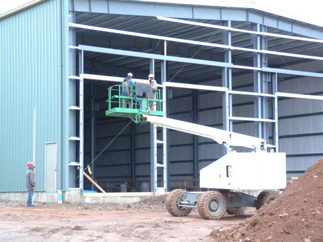
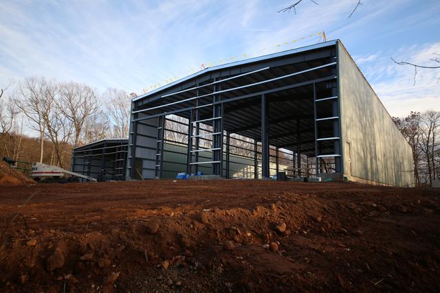
The crane towers over the building 2 site as columns are placed on the
foundation, and wall girts are installed to tie the columns together.
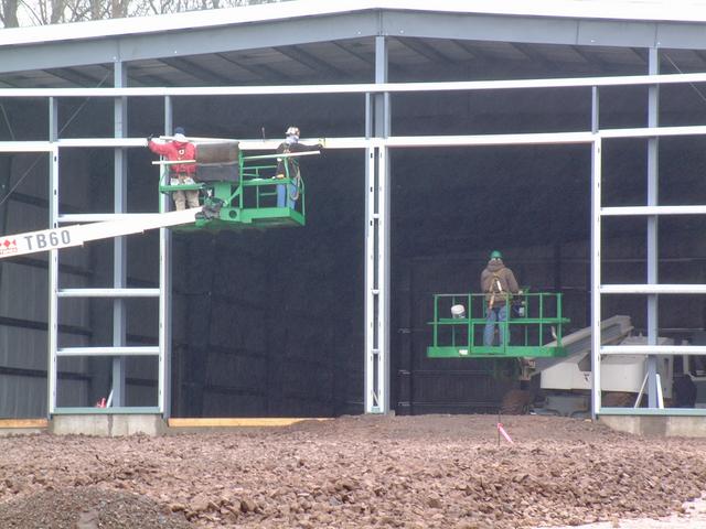
From the aerial lift, two steel workers complete the roof structure at the
front of the building.
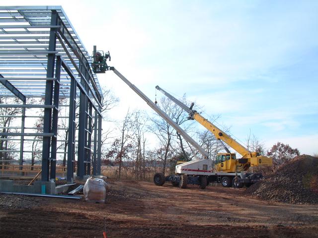
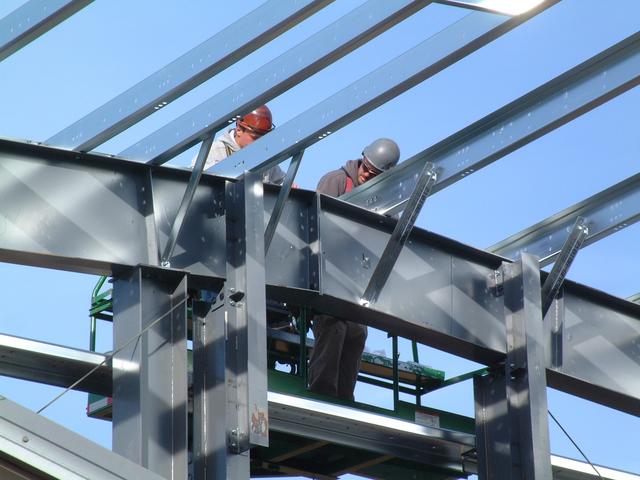
While at the back, one worker installs the end wall girts.
Roof purlin bracing details.
One of the bays contains X-bracing in the roof and walls.
Girt connection details at the front corner the building 2.
Looking into track 4 with the future pit, which has been temporarily
protected with a wooden fence during construction.
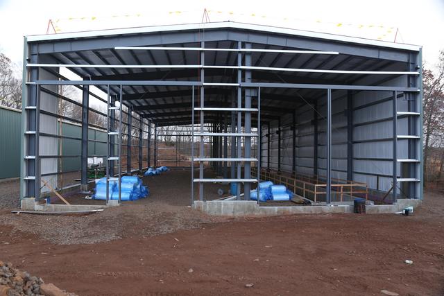
November 15-17, 2013:
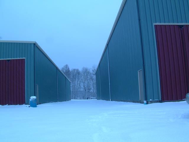
Building 2 is spaced 30' from building 1 (this is a building/fire code
requirement) and is also offset 30' forward (for track design reasons).
The interior row of columns in building 2 is slightly off center.
They are designed to support potential future upgrades: on the right,
a 28' span, 10 ton bridge crane running the length of the building and
spanning two tracks, and on the left a 40' wide storage mezzanine.
These 6-hole plates which were factory-welded to the web of the east and
middle columns are connection points for future mezzanine floor girders.
Close-up view of the factory-installed brackets which will support future
crane beams and rails.
Standing in the "level spreader" stormwater management structure we see
the structural skeleton of building 2, with building 1 in the distance.
The topsoil pile at the rear of the site is one of the few places that is
still higher than the buildings. The 30' strip between the two buildings
will contain 2 dead-end tracks that can be used to store additional cars
in the event of an impending flood.
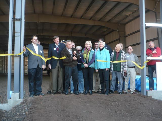
The Ribbon Cutting
November 16, 2013:
About 130 members and friends of the museum were on hand for the
ribbon-cutting ceremony on Saturday, November 16. Unk DaRos, the
retiring First Selectman of Branford, is seen cutting the ribbon
flanked by State Sen. Ed Meyer, State Rep. Lonnie Reed, State Rep.
James Albis, and State Rep. Patricia Widlitz, along with numerous
museum officers and trustees.
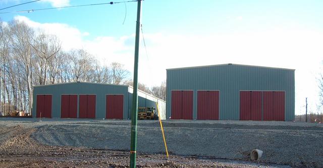
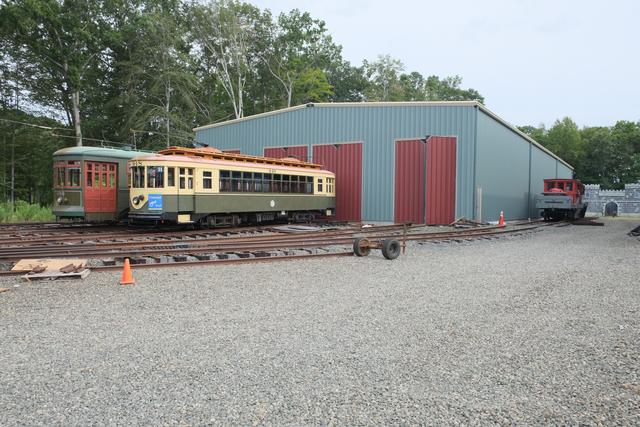
Building 2 completed
November 18-22, 2013:
Following the ribbon-cutting, Building 2 continued to approach completion,
as roof and siding panels were installed.
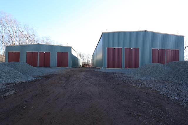
View of building 2 on right, with building
1 visible through the uncompleted side.
Taken from the back of the property
Interior taken from rear of of building 2.
This sequence of photos shows insulation and siding panels being
lifted into place along the side wall of Building 2.
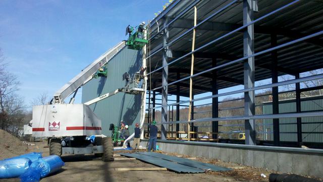
Nov 25 - Nov 30:
Both buildings are now entirely clad, with the exception of the front walls,
pending door installation. Gutters and trim have been completed on building
1, and ongoing for building 2.
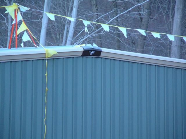
The logo of Varco-Pruden, the manufacturer of the building, is embossed
on this piece which joins the gable trim at the peak of building 1.
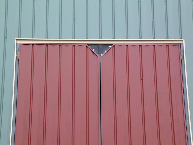
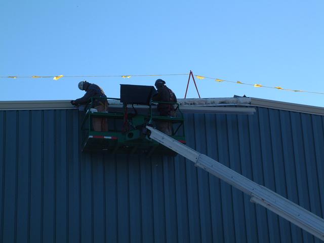
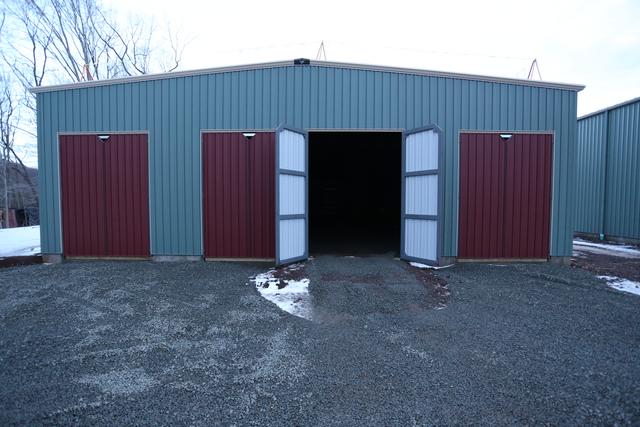
Doors
Dec 3:
The final phase of the building construction is the doors. One set has
been fabricated and test-fitted. The doors are made from welded structural
rectangular steel tubing, and are very substantial. They will be clad to
match the building finish.
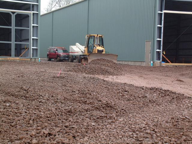
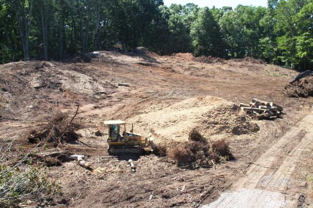
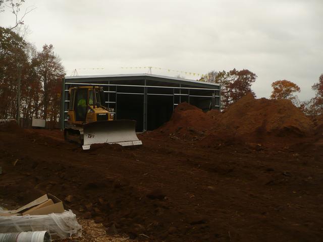
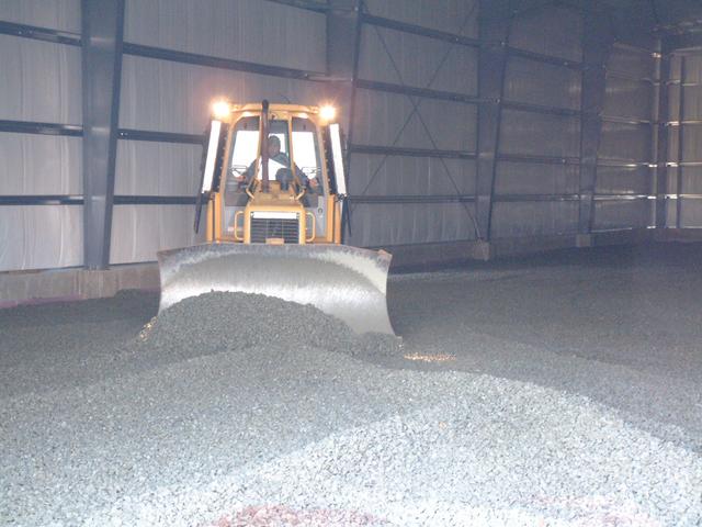
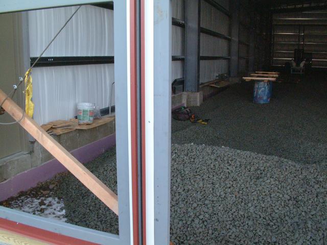
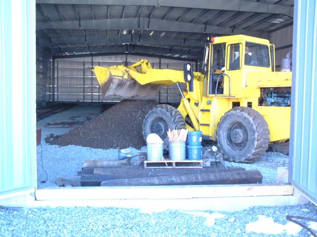
Final Grading and Site Work
Dec 16-24, 2013:
The site work contractor is wrapping up the final grading. Ballast stone
is being spread on all of the track areas, and also inside both buildings.
The contractor will leave a finished grade which is approximately one foot
lower than the ultimate rail head height, then the museum will place ties
and rail. Below a dozer spreads stone within building 1.
There are two concrete drainage pipes which pass beneath the ramp approaching
new building 2. In the event of another severe flood, these are designed
to relieve the water pressure against the side of the ramp, and to allow
water to drain back out.

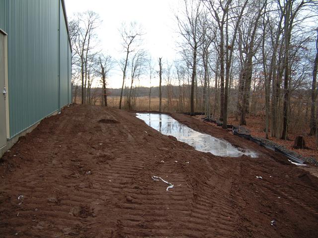
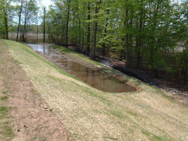
The storm water detention pond has been completed along the side of
building 2. Runoff from the two building roof drains is diverted into
this swale, which in the spring will be topsoiled and seeded to provide
a natural buffer against erosion.
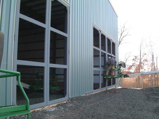
Building 2 Trim Done
The last bits of trim have been installed on Building 2 across the front
wall. Below: the steel workers cut a piece of trim to length and put it up.
Doors in Progress
All of the trackway doors (4 sets on each building) have been hung, and
sheathing is almost complete. Below: On Dec 16, building 1 doors are up
but no sheathing is in place.
Door hinges being secured on the last of the door frames at building 2.
These J-shaped moldings retain the corrugated siding and make a weathertight
seal.
The following week, all doors are clad on building 1, and almost done on
building 2.
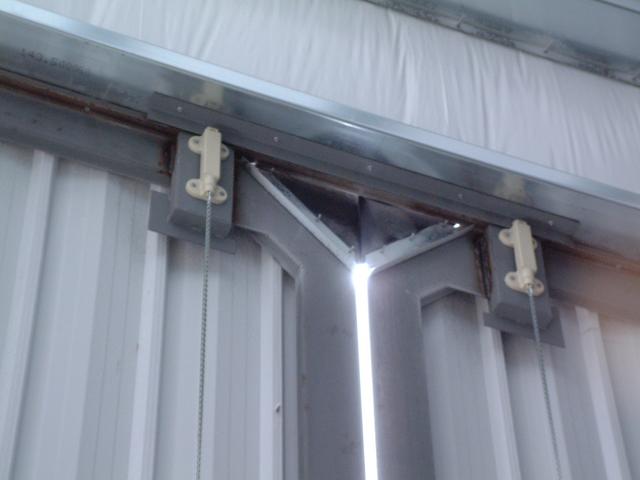
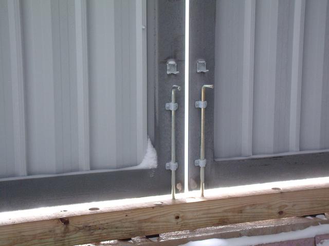
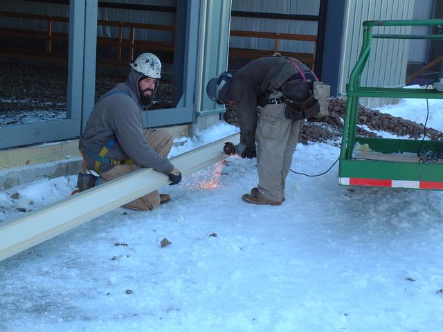
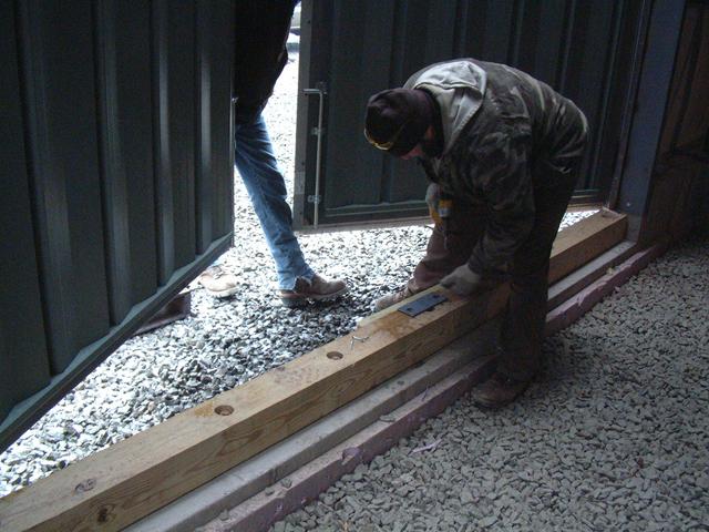
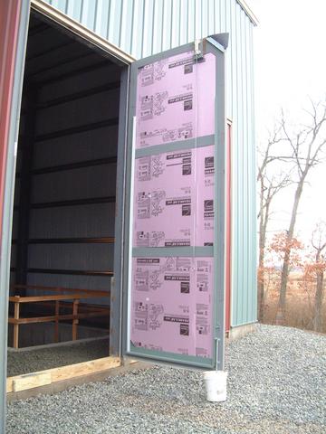
The Last Little Building Details
Jan 6, 2014 - Jan 17, 2014:
The last few details of the two buildings have been wrapped up. Braving the cold, these two construction workers completed installation of the bottom bolt plates, edge weatherstripping, bottom door sweeps, insulation and innner cladding.
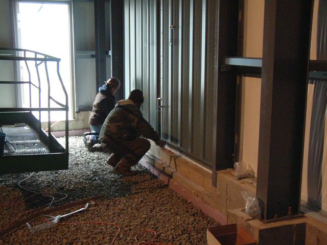
Door panel of building 2(9) just prior to inner cladding installation shows the 2" rigid insulation.
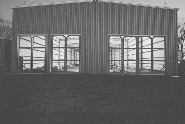
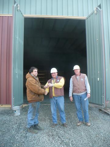
Finally, both buildings are done...
And Munger Construction has literally handed us the keys to the building!
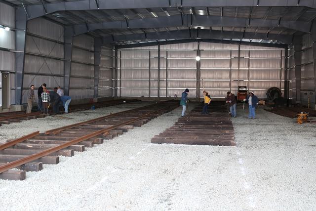
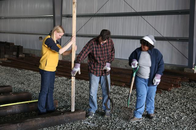
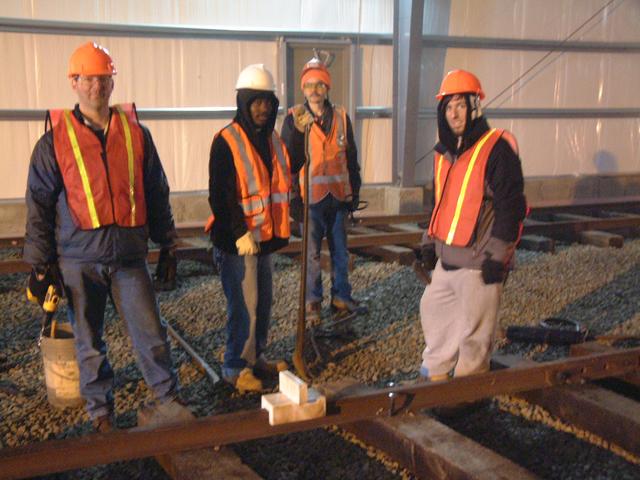
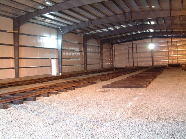
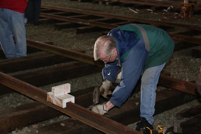
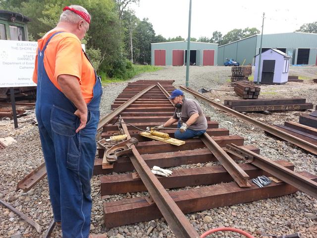
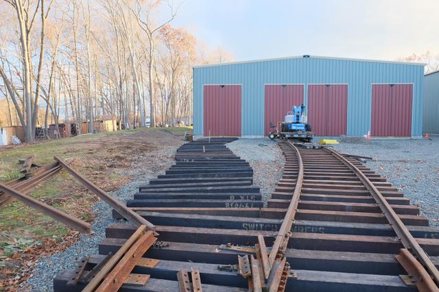
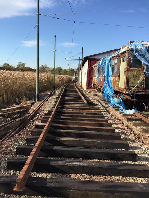
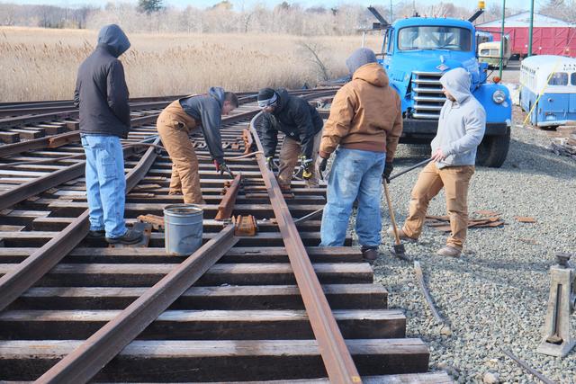
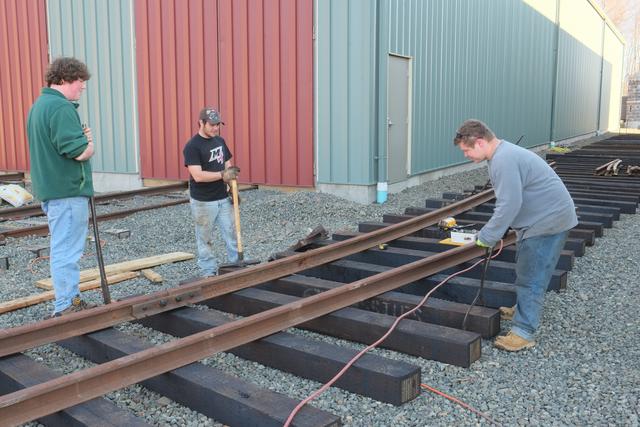
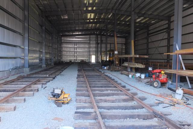
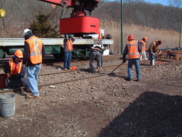
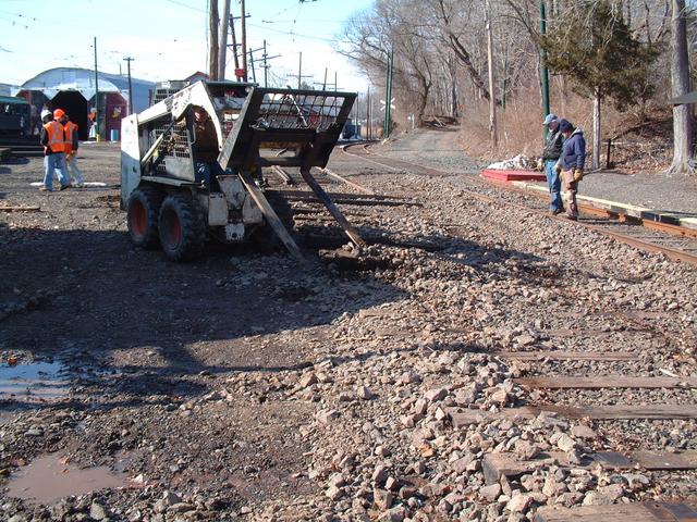
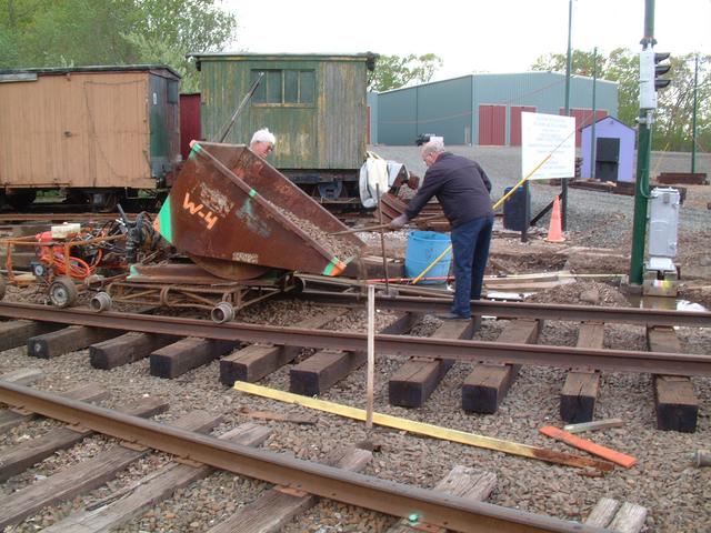
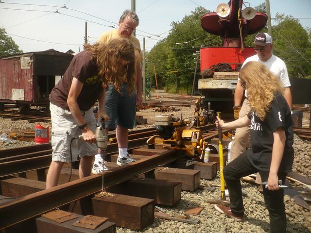
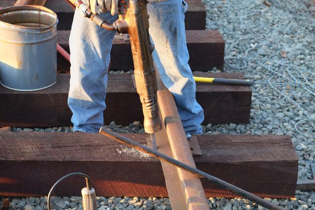
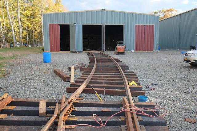
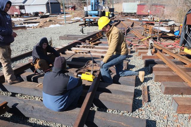
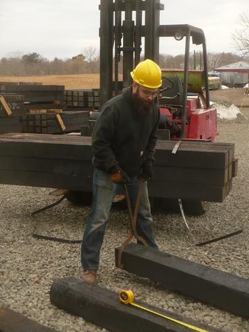
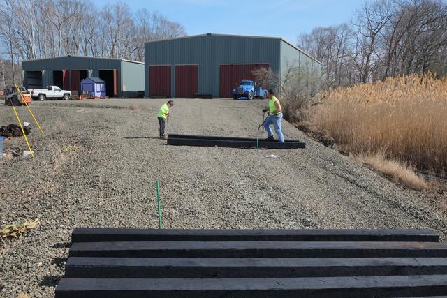
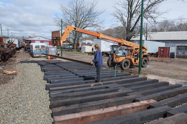
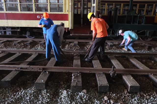
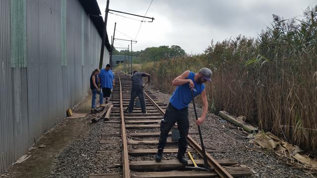
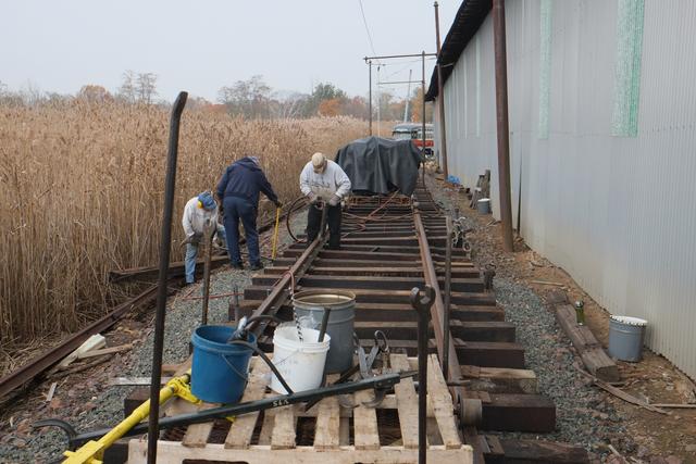
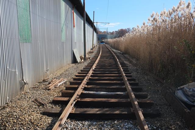
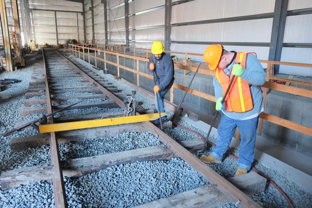
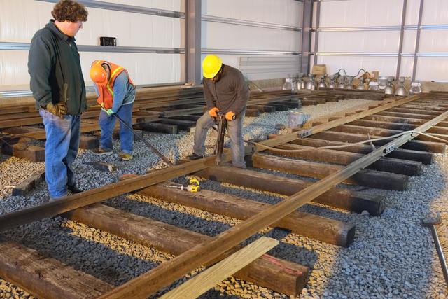
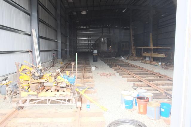
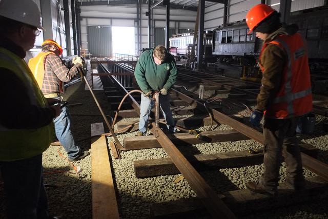
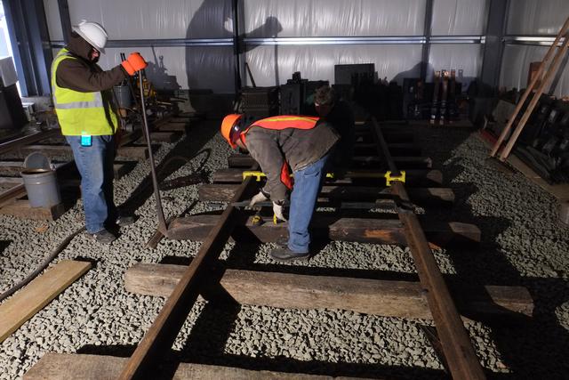
Track Installation Begins
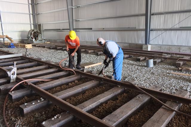
On Jan 18, 2014 we had our first "work party" for Elevating the Collection.
The task at hand was to begin installation of the tracks within building 1(8).
Work began at 10 AM. Layout lines for the first two tracks had already been
put down the day before.
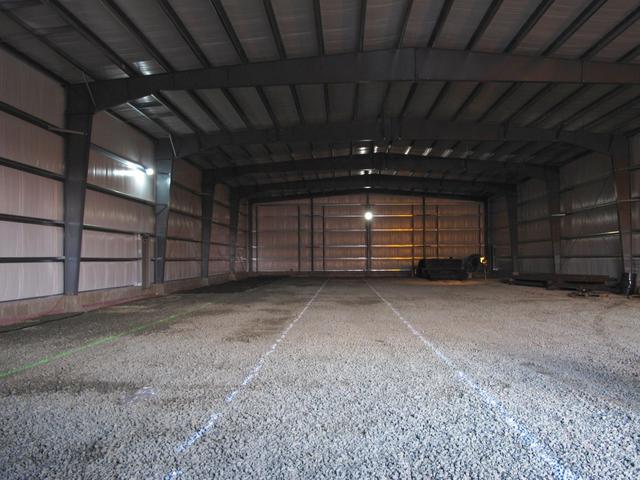
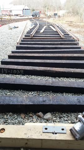
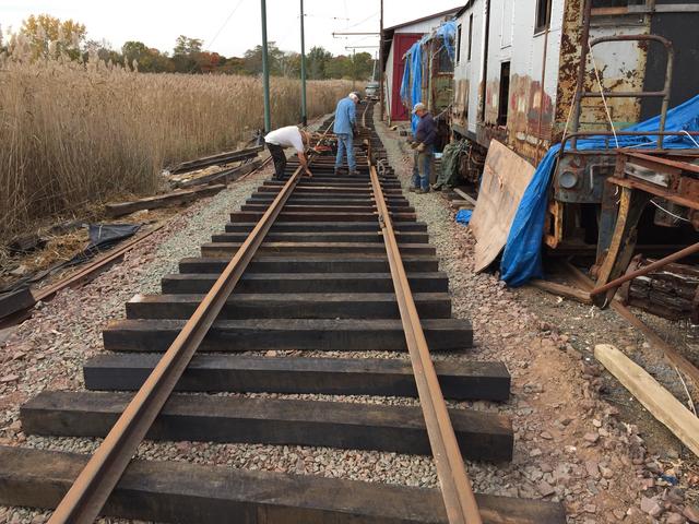
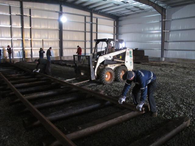
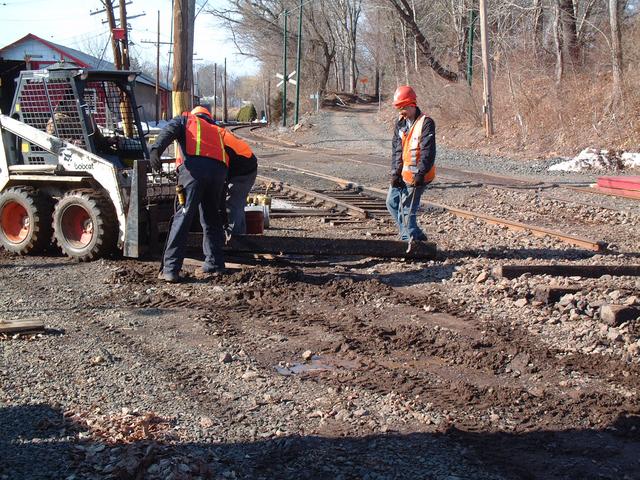
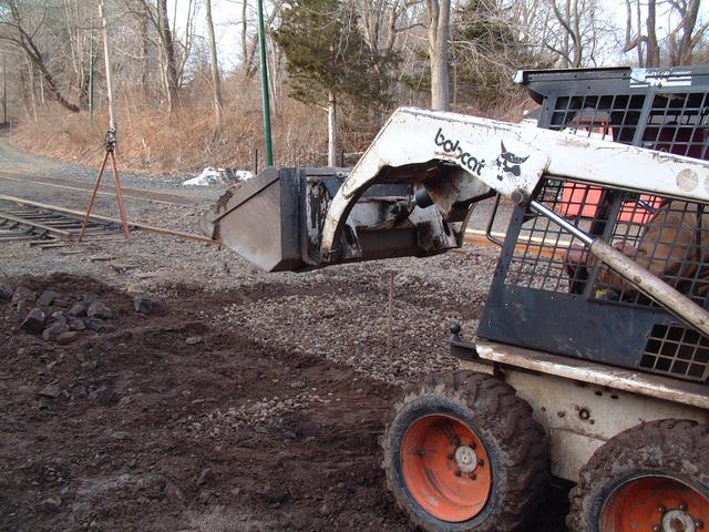
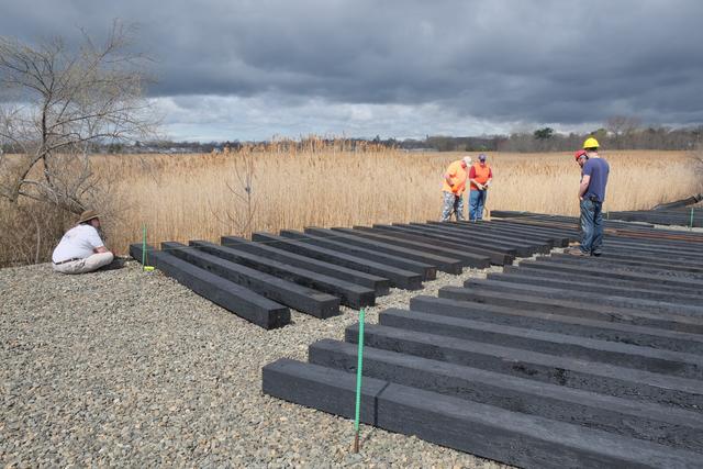
Ties were distributed with the Bobcat machine and spaced by hand every
3 feet or so, using the layout guide lines to align the edges of the ties.
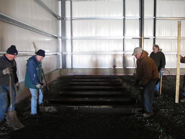
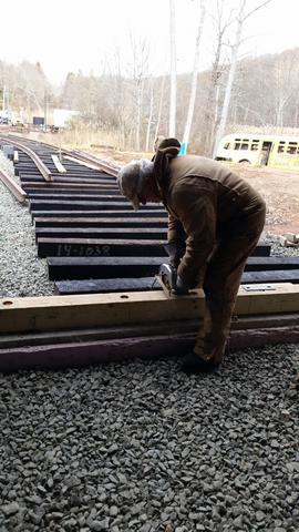
The ballast stone was dressed by hand to provide an even bearing for the ties
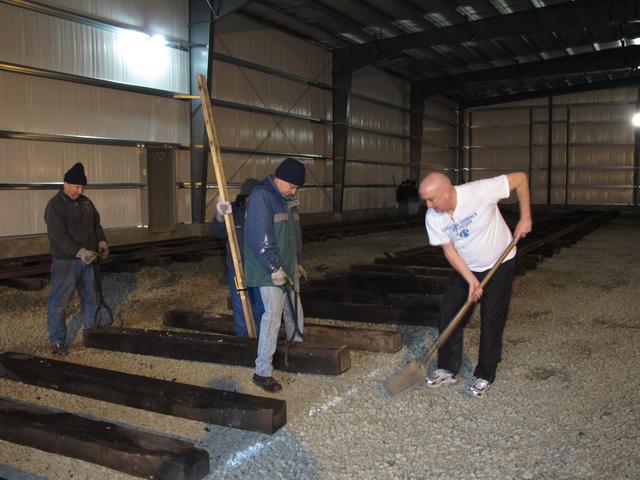
Rough elevation was checked with a rotary laser level. At a later date,
additional ballast will be spread over the tracks and they will be raised
up and tamped to final elevation.
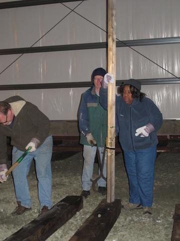
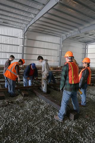
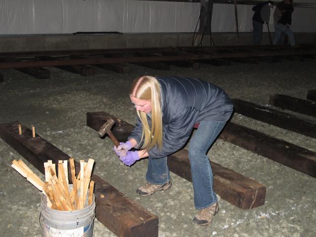
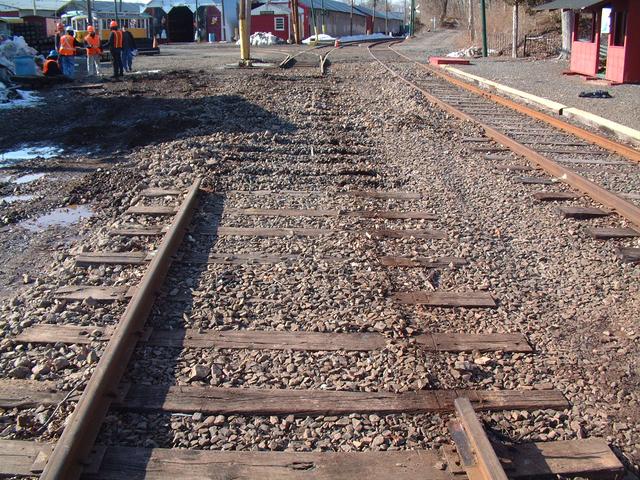
For these tracks inside the buildings, where traffic will be light and
exposure to the weather will be zero, we saved a lot of money by utilizing
used ("re-lay") ties. The old spike holes need to be plugged up.
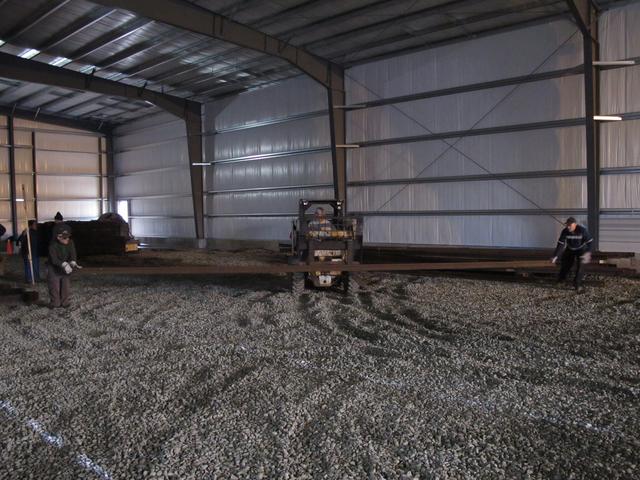
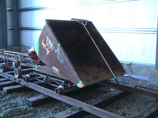
Once a stretch of ties was put down, the Bobcat brought over one rail
at a time (about 30 feet long) and set it down. This is the used 60AS
rail which was donated by National Capital Trolley Museum. The light section
is suitable for track inside the building.
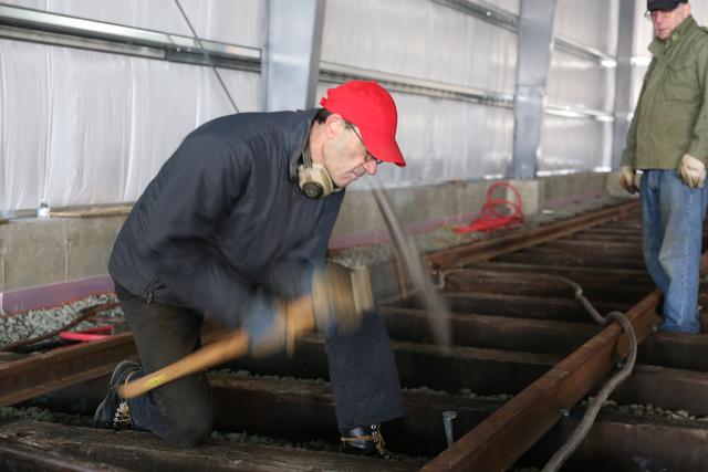
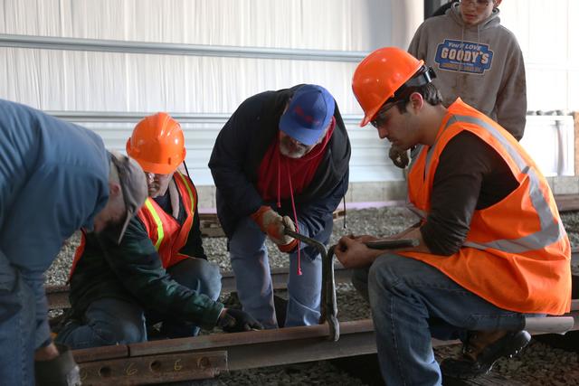
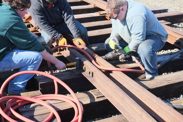
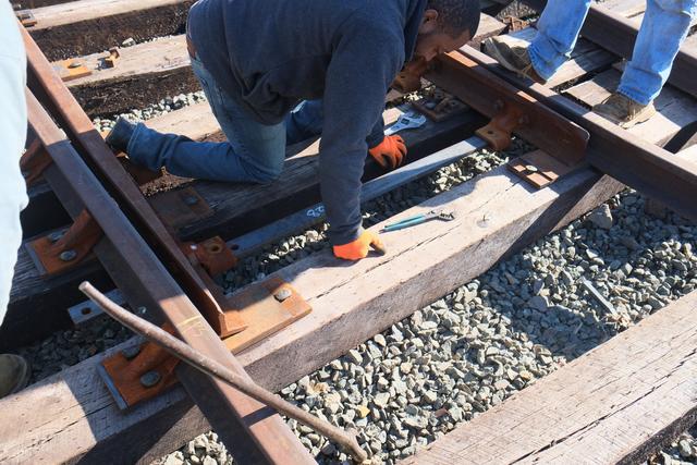
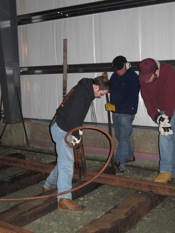
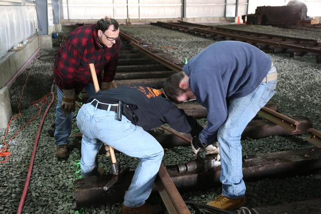
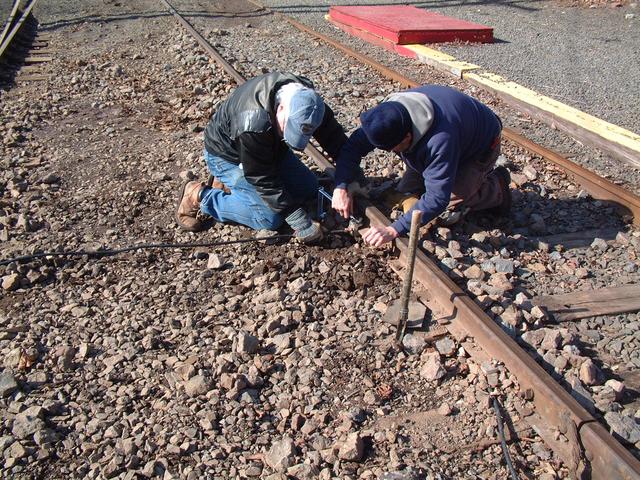
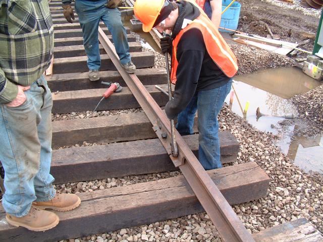
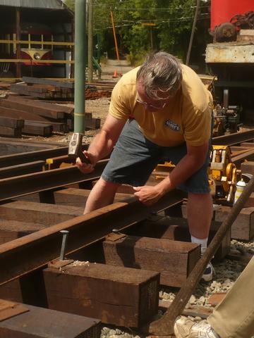
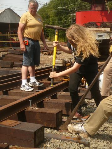
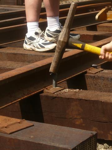
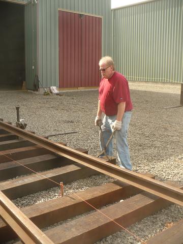
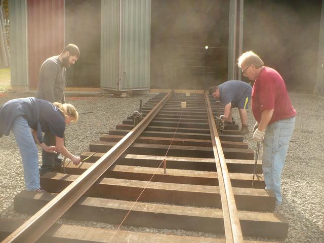
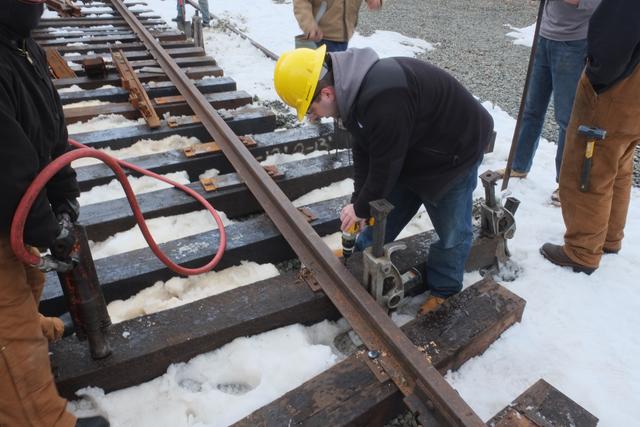
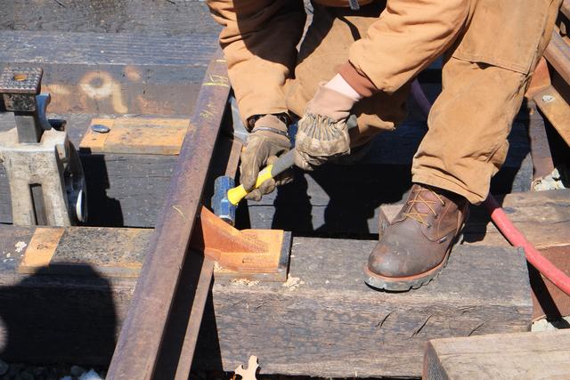
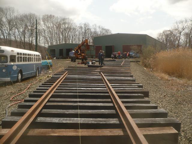
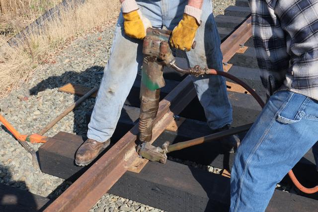
When laying new track, one rail is selected as the "line rail" and is spiked
to line. The other rail is then spiked to gauge (56.5") relative to the
line rail. We began on track 81 and used the concrete foundation wall as
the reference for setting the line rail. One or two volunteers held the rail
at the proper position while another tapped the spikes in loosely by hand,
and then yet another volunteer came along with the pneumatic spiking hammer
to drive each spike down. As the tie tends to settle down into the ballast,
another volunteer holds up the end of the tie with a bar.
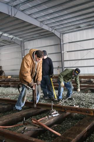
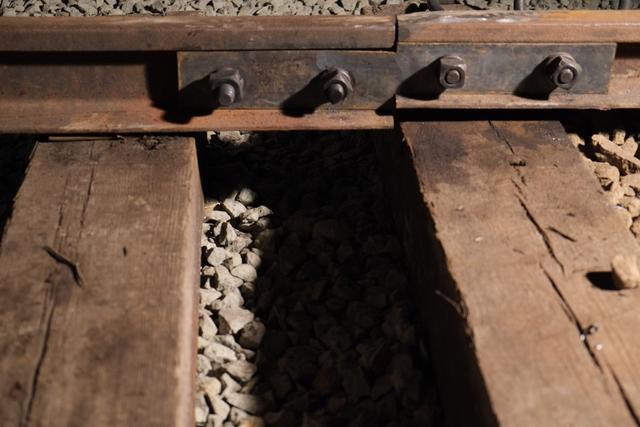
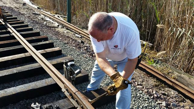
As the end of each length of rail is reached, the next length is jointed up.
We used a pneumatic wrench to speed the process of tightening the track bolt
nuts.
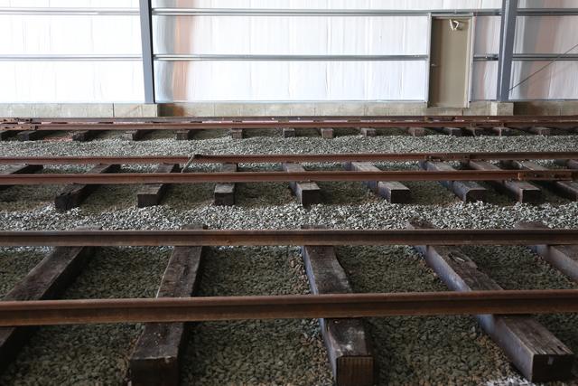
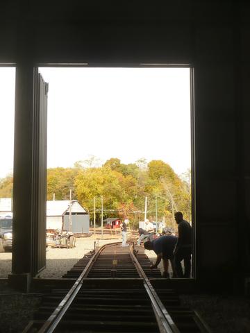
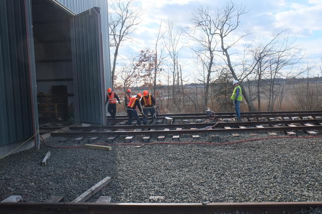
By about 4PM, it was starting to get dark, cold and windy, so we called it
a wrap, cleaned up the work site and secured the building. Ties and rails
had been distributed the length of tracks 81 and 82, and the line rail was
complete on track 81. Work will continue in the coming weeks and months.
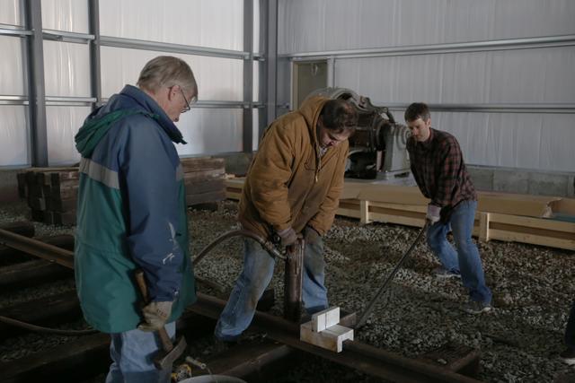
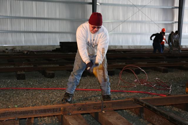
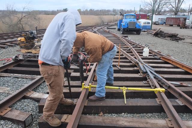
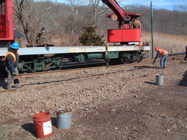
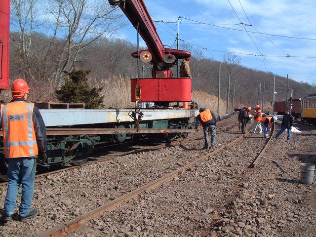
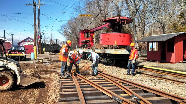
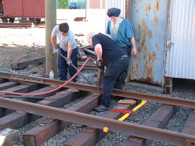
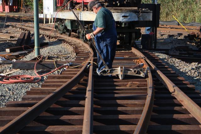
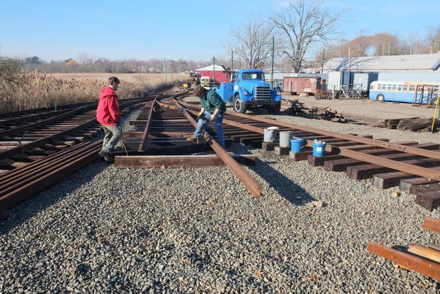
First Main Line Switch cut-in since the 1970s begins
Mar 14, 2014
It was sometime in the Ford administration when the museum's main line track
was last cut to install a switch! Finally after a seemingly endless snowy
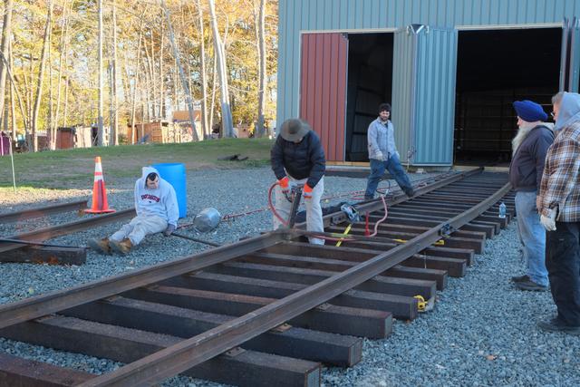
winter, the weather improved sufficiently to begin this project.
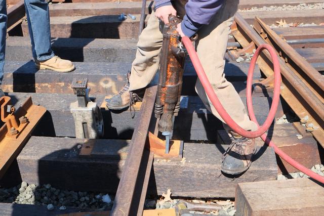
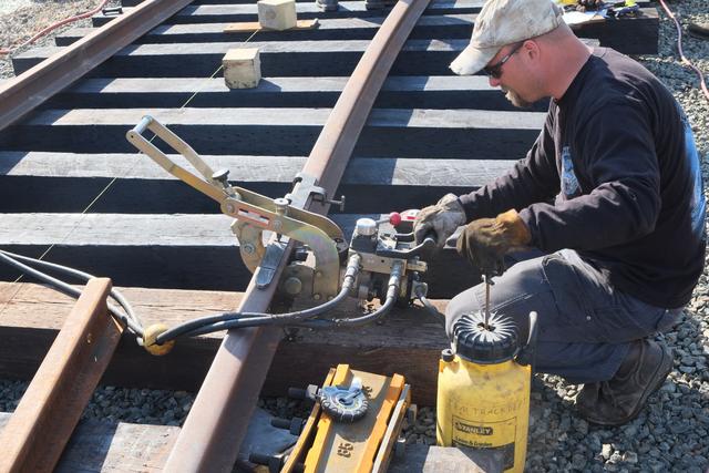
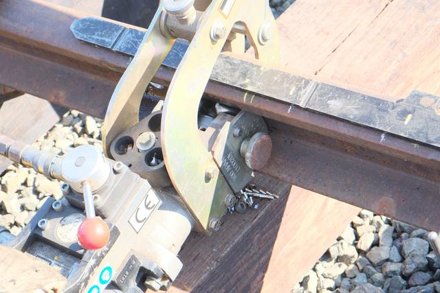
Above, unbolting joints on the existing 78NH mainline rail. Below, using
a hydraulic spike puller really made the job go a lot faster.
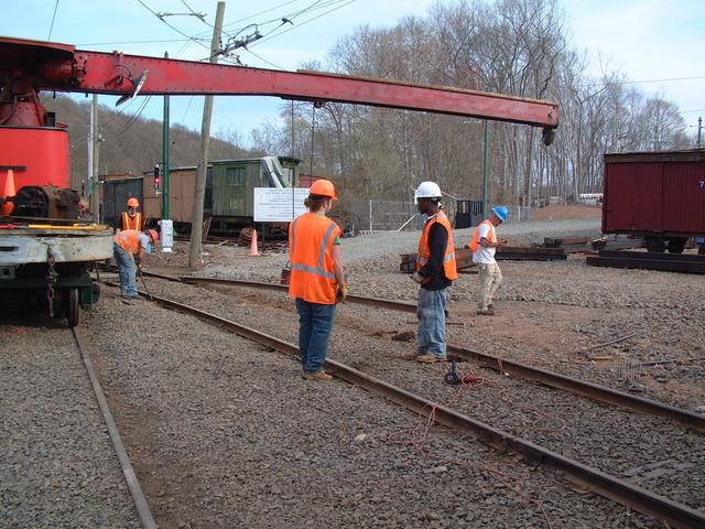
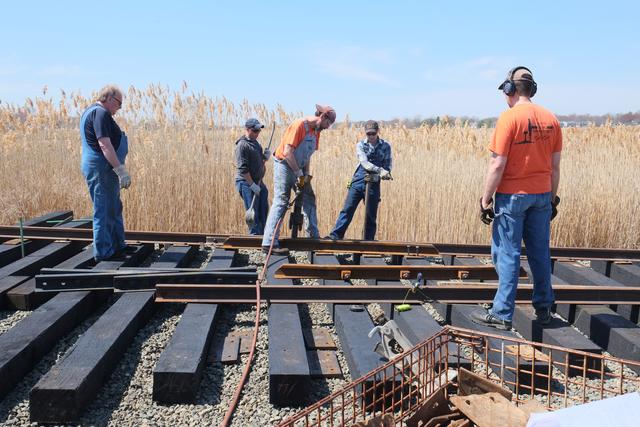
With a large group of GWCC and museum member-volunteers, several gangs were
at work at once getting the rail prepared for removal.
These traction power return bonds had to be ground off prior to separating and
removing the lengths of rail.
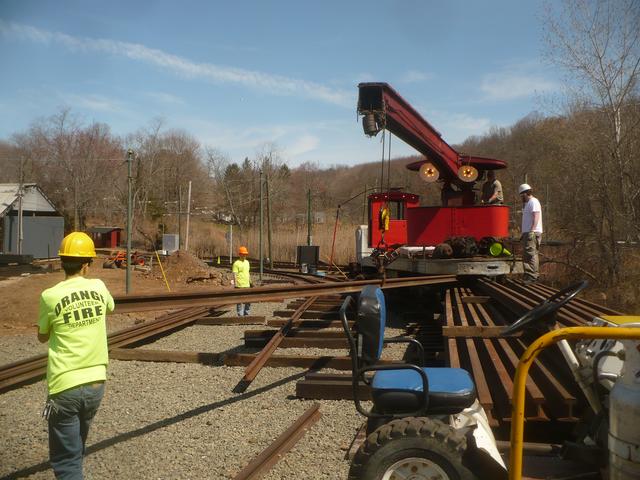
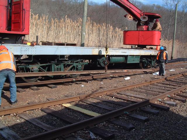
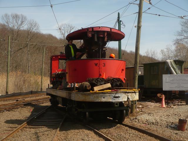
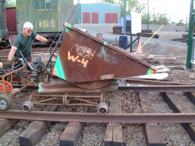
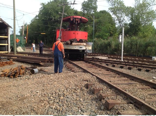
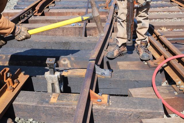
Now it was time to lift out 4 sections of 78NH rail and set them aside.
Rail tongs are applied to the center of each section and crane W-3 then
lifts the rail.
Two volunteers "walk" the rail along a short distance and then set it
down outside the work area.
Rail removal progresses
The tie plates which were under the rails are carefully picked up and
stacked for future re-use.
The 'Bobcat' comes along and picks the old ties out of the ground, then
moves them out of the work area. The ties were sorted into 3 piles: good
for re-lay (some of these ties had just been installed last year), good
enough for temporary track, and discard.
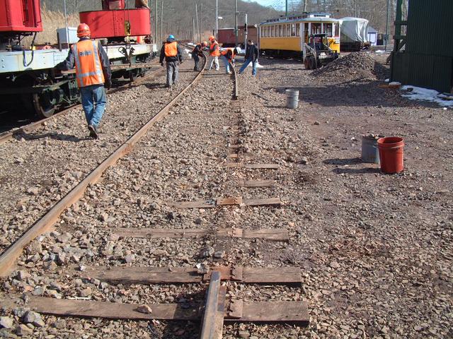
The sight of the missing stretch of track is somewhat intimidating.
Volunteers in the signal department install a temporary jumper. With
one of the main line tracks cut, this is needed to provide a redundant
path for traction power return to the substation.
The Bobcat comes back and cleans up the roadbed where the old ties had been
removed, and then spreads and levels some stone to support the new ties.
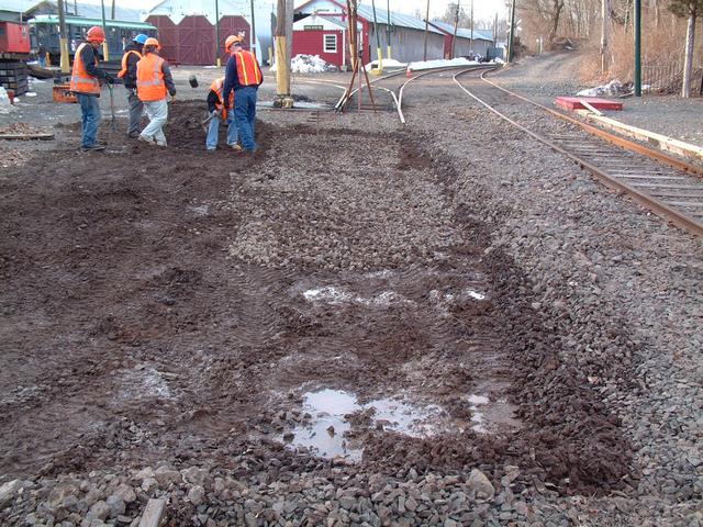
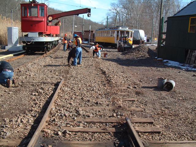
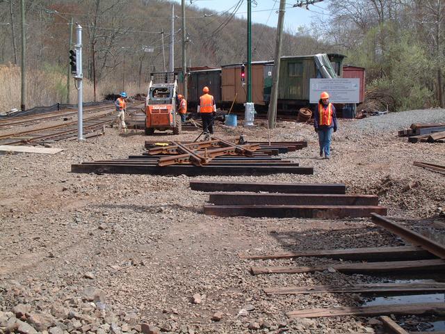
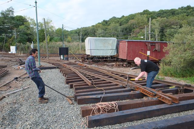
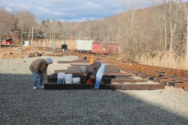
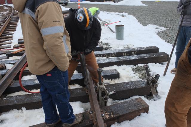
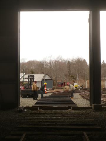
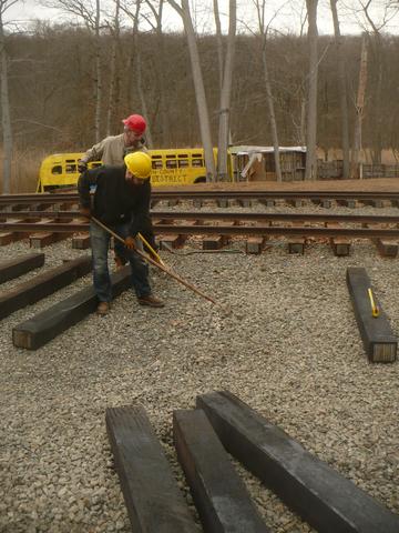
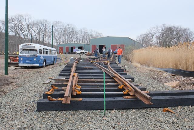
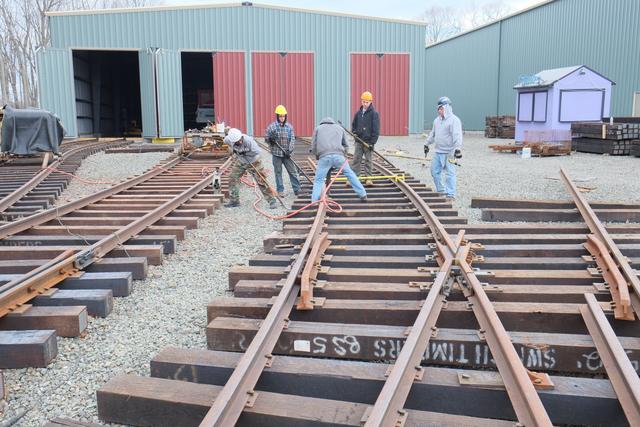
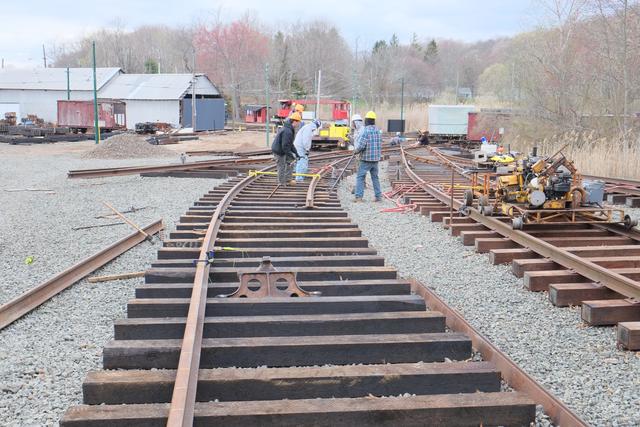
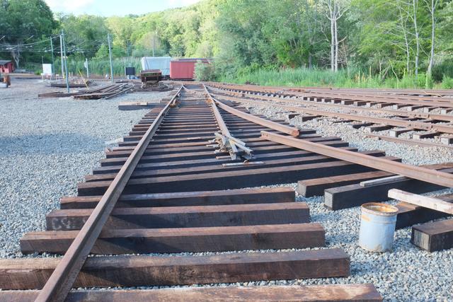
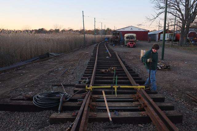
Now the work of setting out the ties can begin. The turnout begins with two
'headblock' ties 15' long which will support the switch stand, then forms a
triangle getting wider as it goes from the points to the frog. Crane W-3
was used to bring ties from the tie pile and place them into rough position.
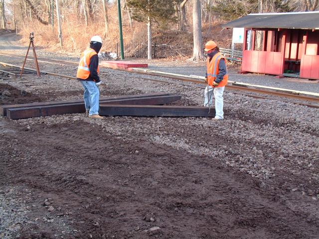
After being roughed-in, the ties were lined up and spaced following the
drawing layout. The next step will be the installation of the rails.
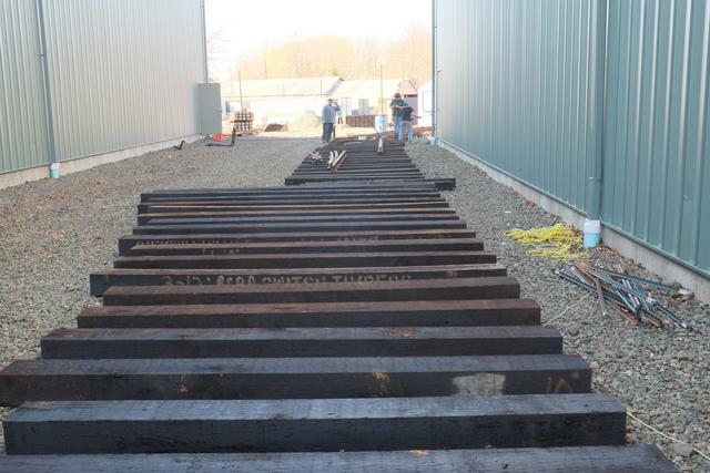
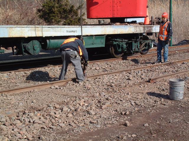
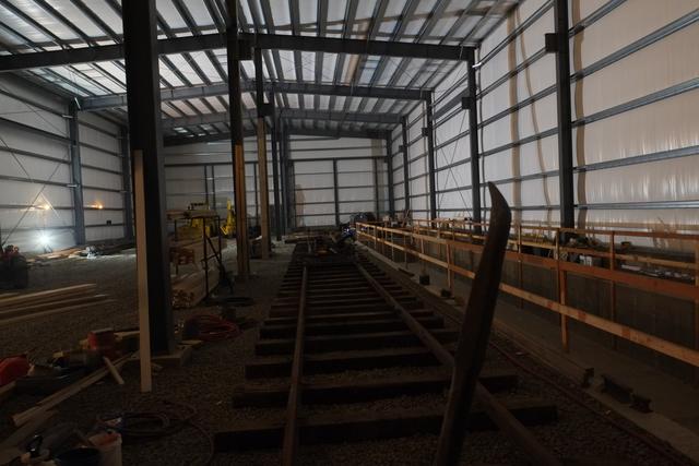
Meanwhile, back on the hill
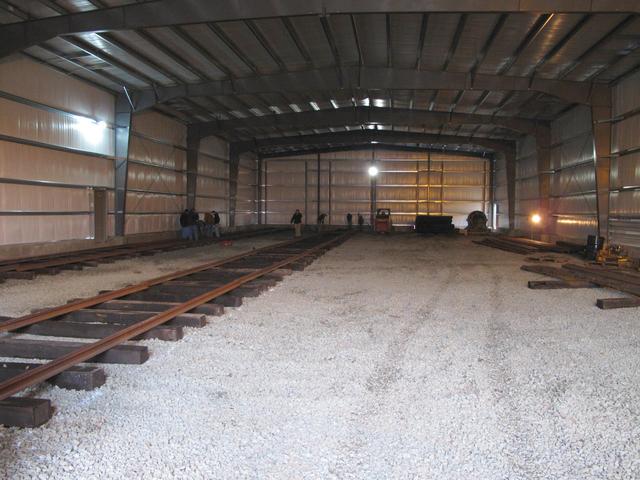
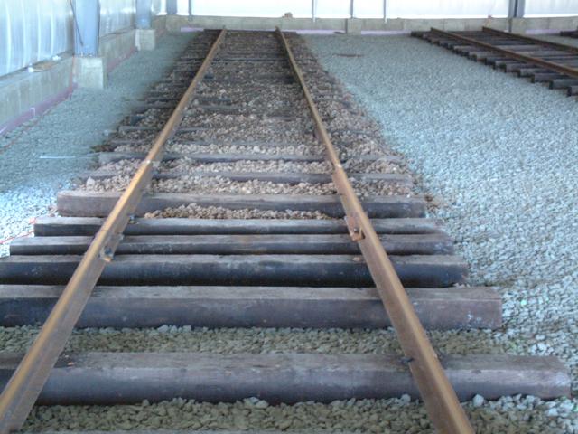
During the last weeks of February and into early March, museum volunteers
working alongside GWCC volunteers completed 3 tracks inside the building and
roughed-in the 4th track. Only 81 track is complete to the door. The other
3 tracks are being left about 30' short right now to facilitate movement
of heavy machinery within the buildings.
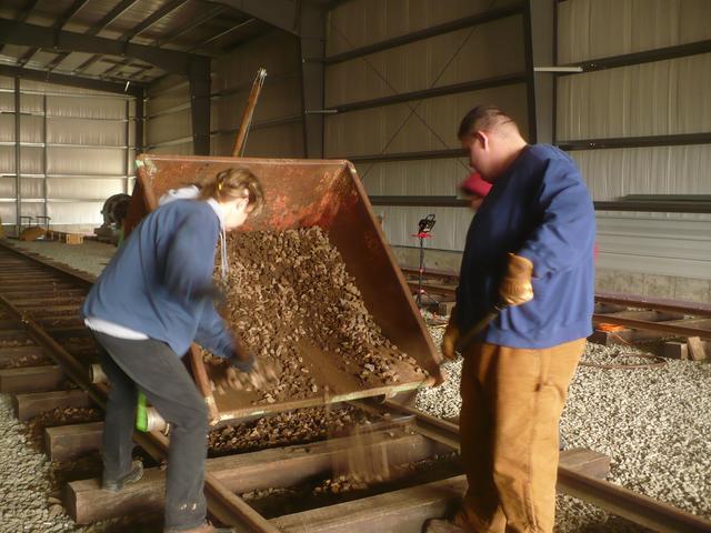
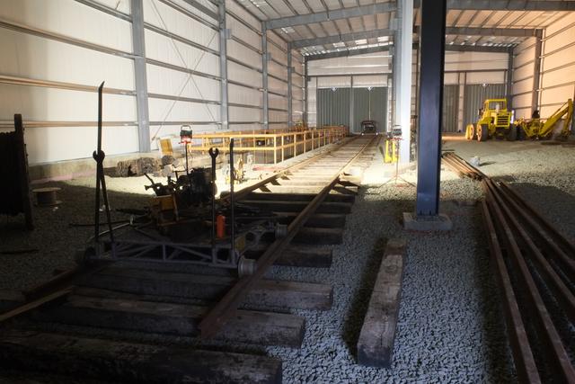
Above the large payloader delivers a few yards of stone and stockpiles it
within Building 8. The contraption below is a home-made 1/2-yard hydraulic
dumper mounted on a track cart. The stone is loaded from the pile into
this bucket using the small 'Bobcat' and then spread along the track.
Once the stone is spread, each track will be jacked up, leveled and tamped.
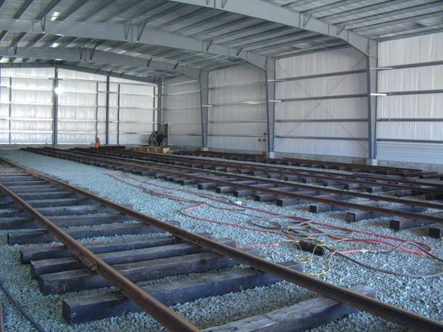
Above, view of all 4 tracks inside Building 8.
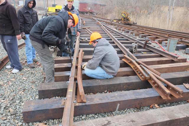
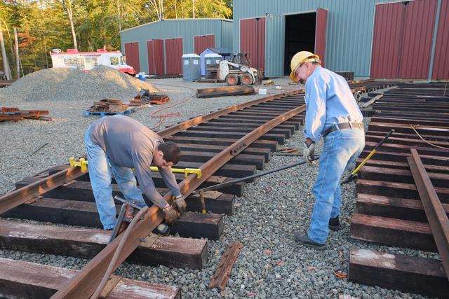
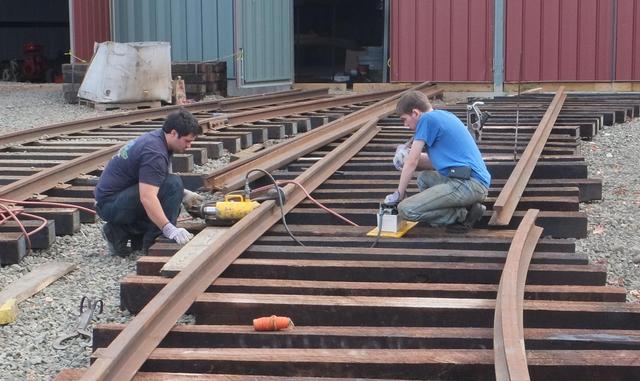
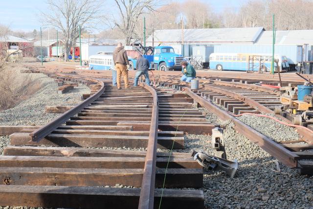
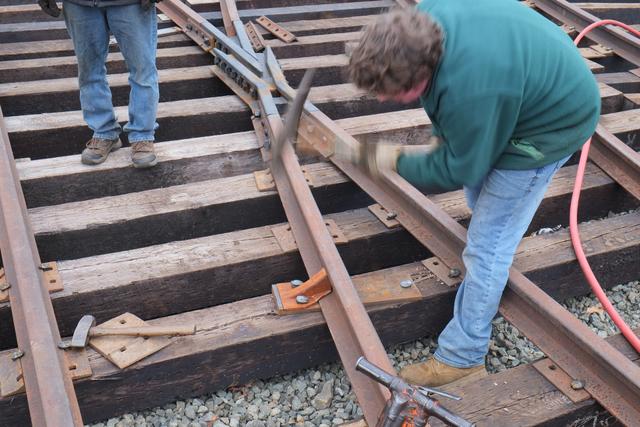
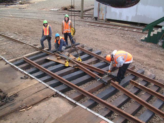
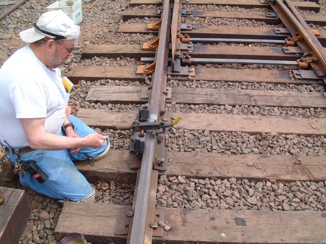
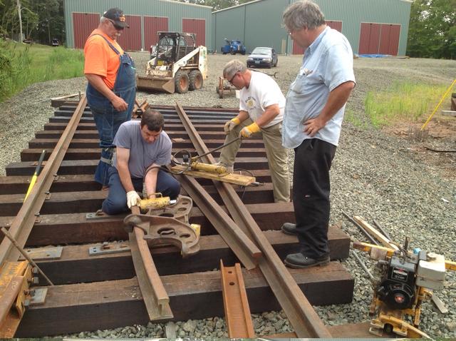
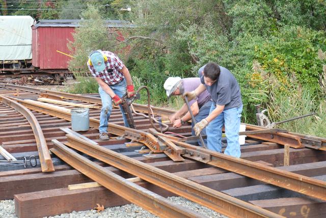
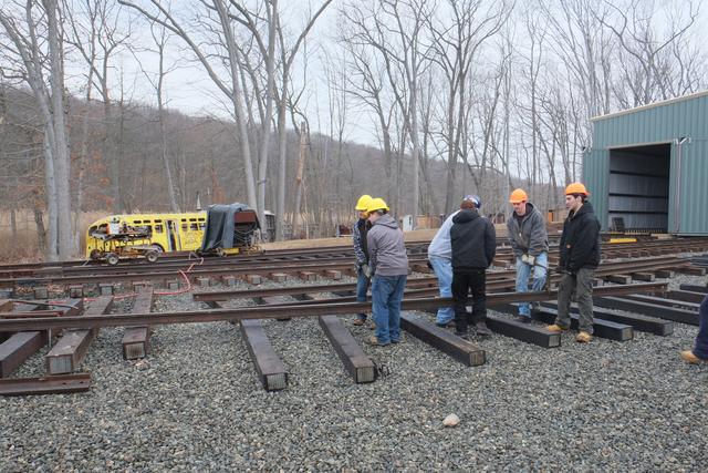
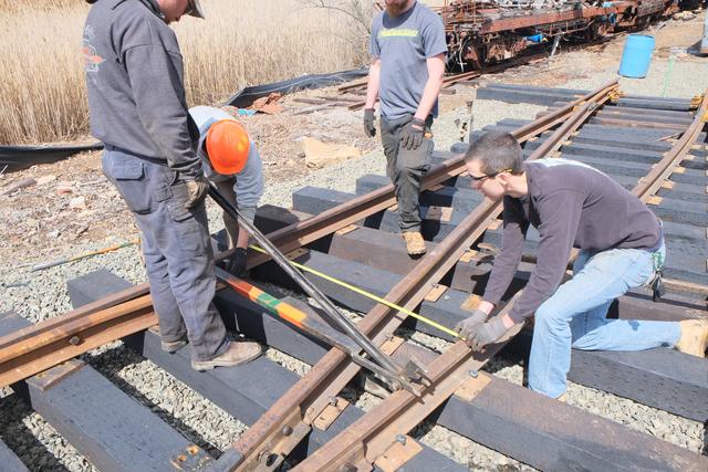
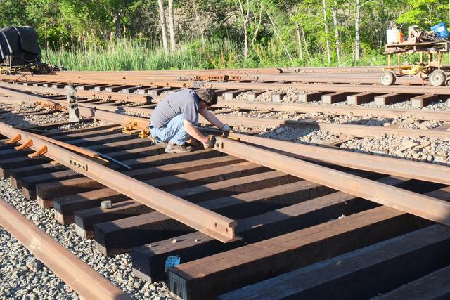
Main Line Turnout Installation
Mar 17-21, 2014:
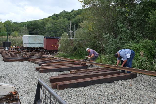
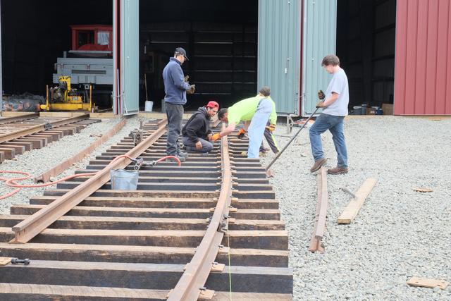
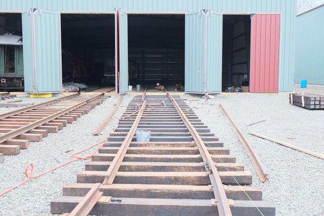
With the switch ties placed and roughly aligned and leveled, the process
of installing the actual turnout began. Crane W-3 was used to pick up
the rails (stock rails, closure rails, switch points and guard rails)
which had been stockpiled and lay them out on the ties. Gateway College
Students Kurt, Cameron, Jeremy and Darrell are seen handling the material.
This #4 double-spring frog, below, was handled using special plate clamps.
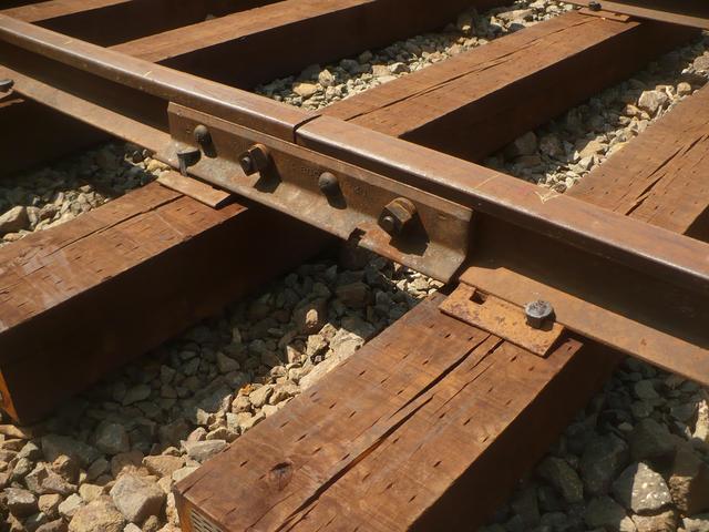
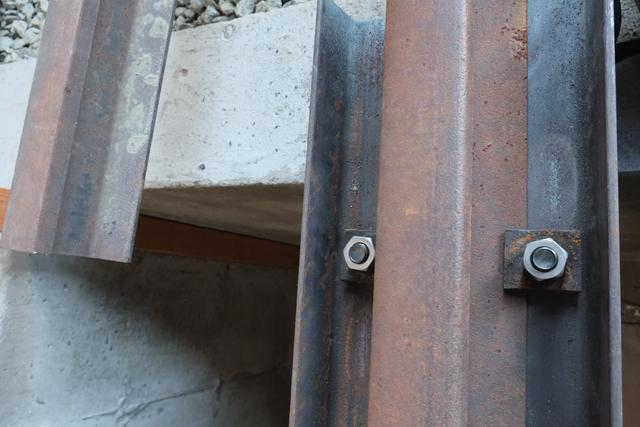
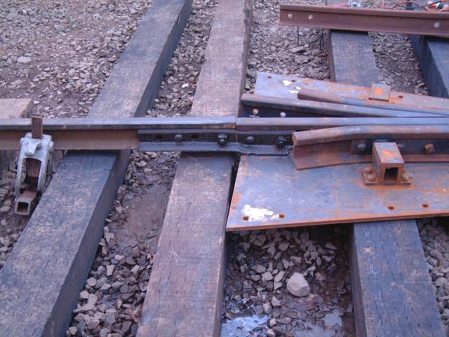
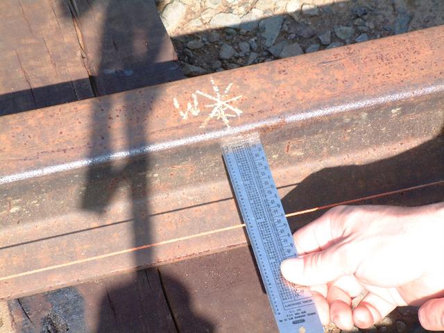
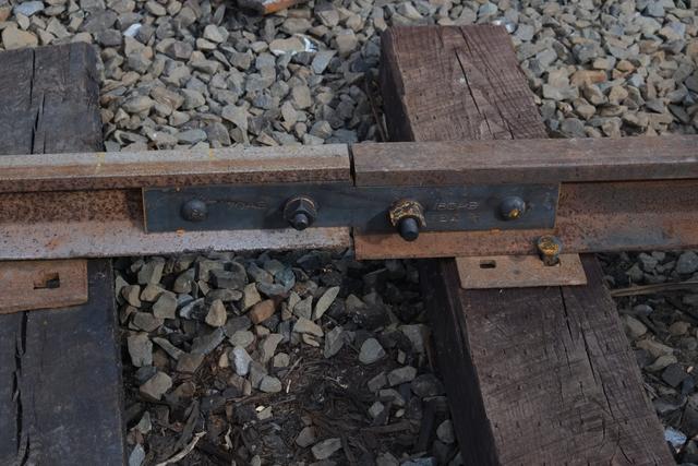
The existing mainline track in this area is 78NH (New Haven R.R.) section.
This rail was obtained used in the 1960s and was installed by museum
volunteers to replace the heavily worn 80AS rail which had been left from
the line's Connecticut Company days. Since 78NH is not being rolled new
anymore, the museum decided to standardize on 80AS for all the new trackage.
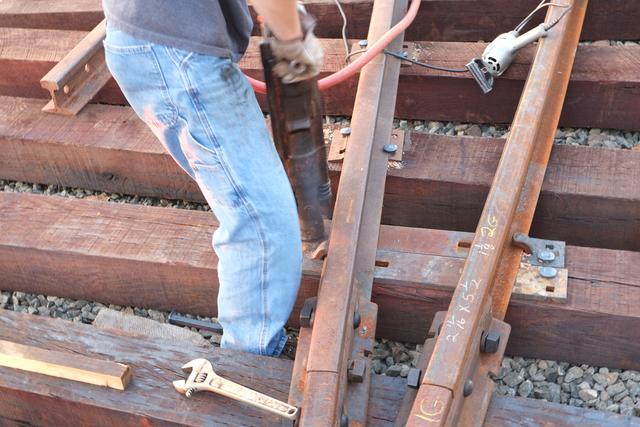
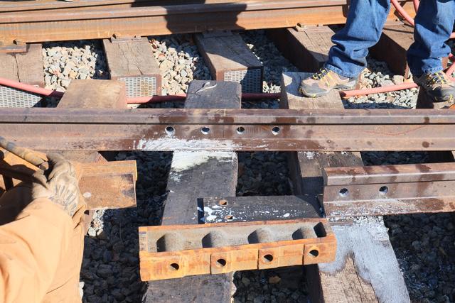
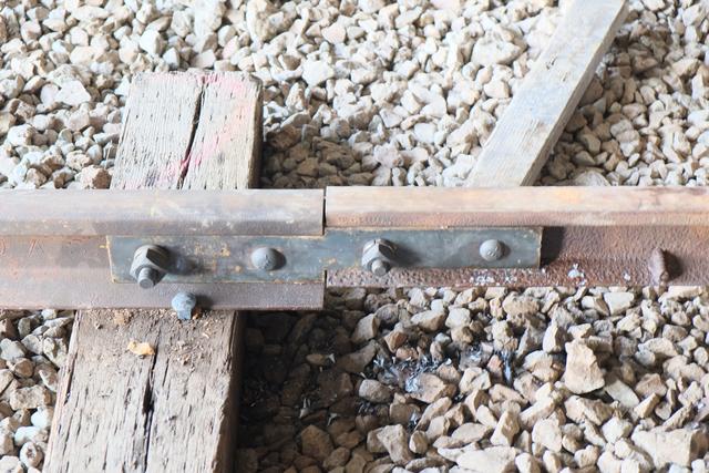
Thus a "compromise" joint is installed between the 78NH existing rail on
the left and the new 80AS frog on the right. The ties have not yet been
aligned, raised and tamped to support the joint.
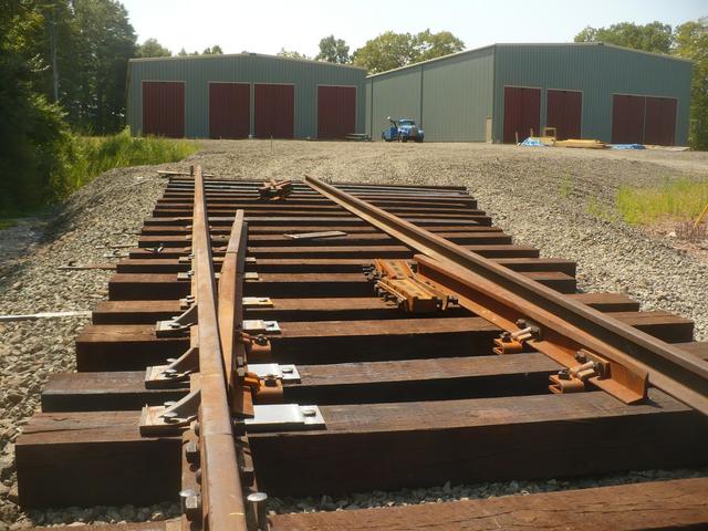
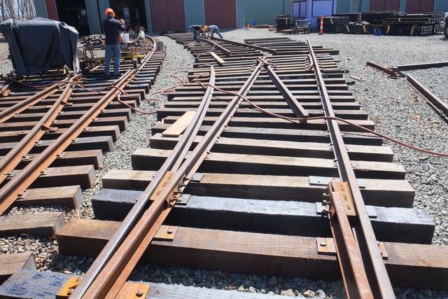
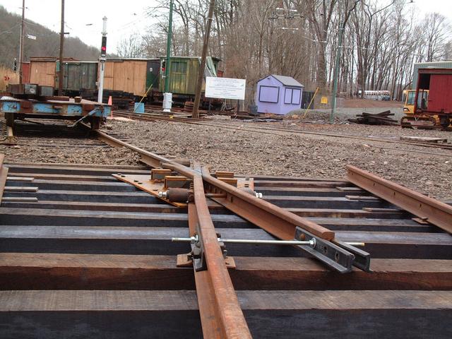
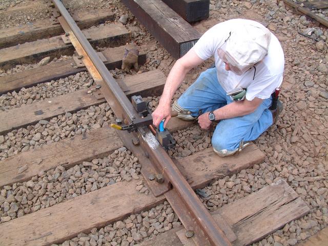
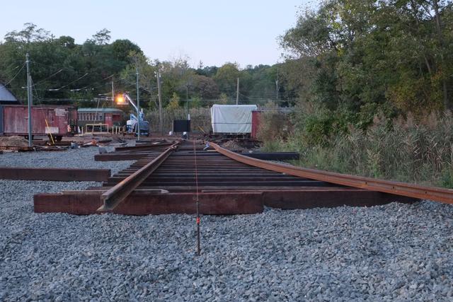
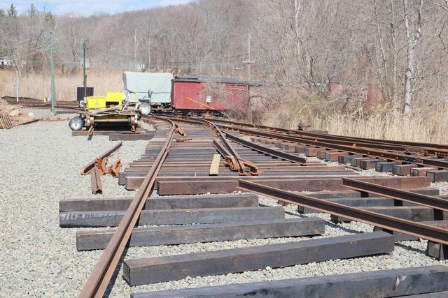
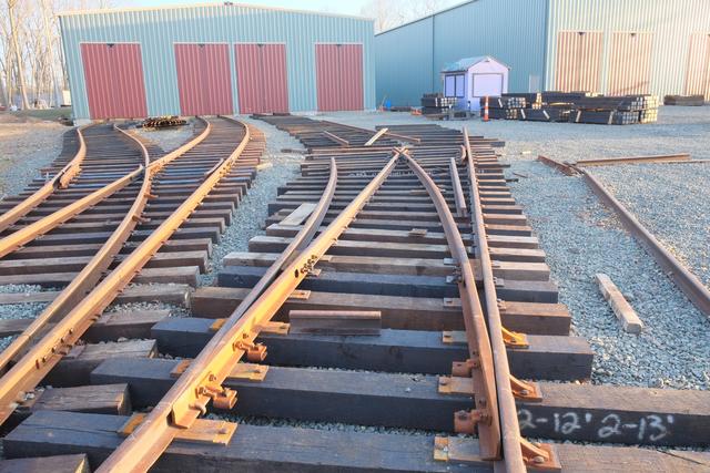
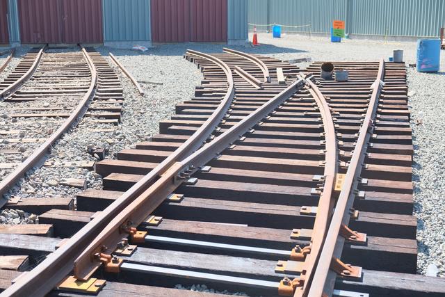
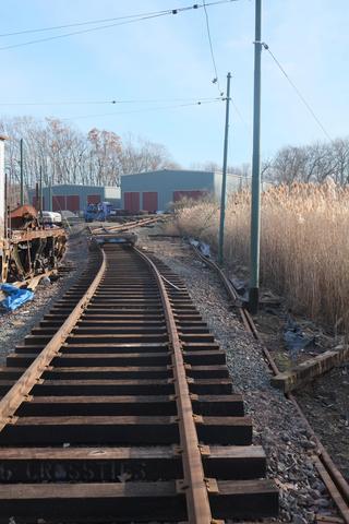
The angle of the frog was established by sighting along the gauge line of
the rail towards a stake that had been set in the distance by means of
surveying instruments. The track diverging to the right will not be
going through the line pole as it might seem: it will take a slight
further right curve before crossing the Narragansett siding track ahead.
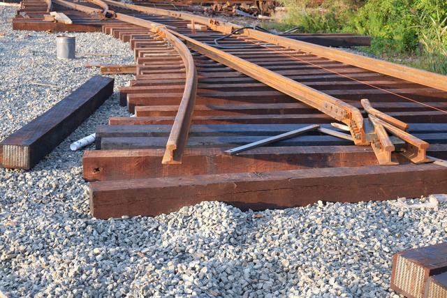
The threaded rod is a temporary measure to hold the wing rails, both
of which can swivel in this double-spring frog configuration, to the
correct "spread."
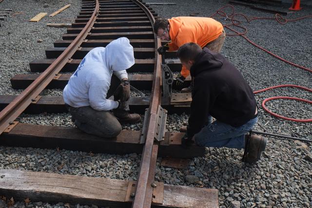
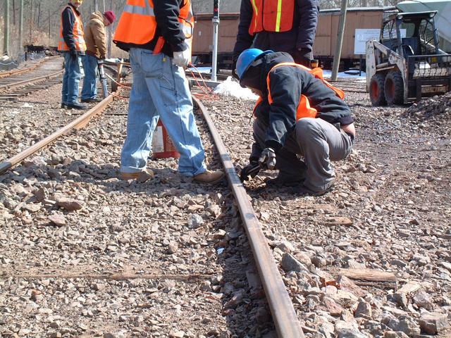
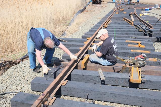
After alignment, the frog was spiked down. Here a museum volunteer joined
forces with a Gateway College student volunteer, both named Joe oddly enough.
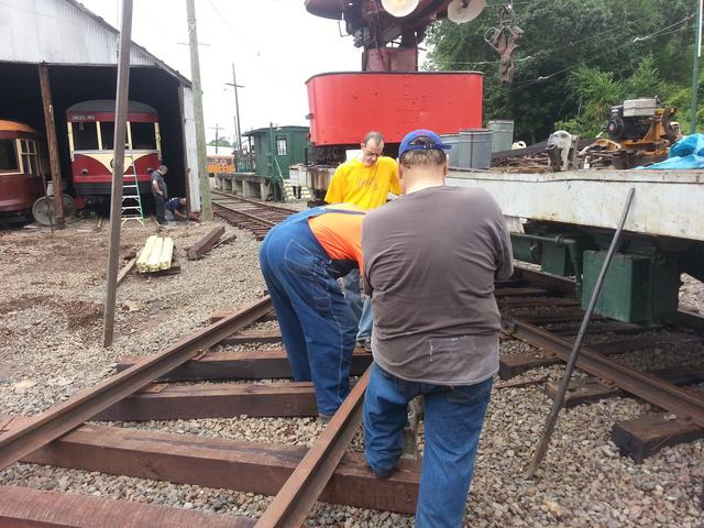
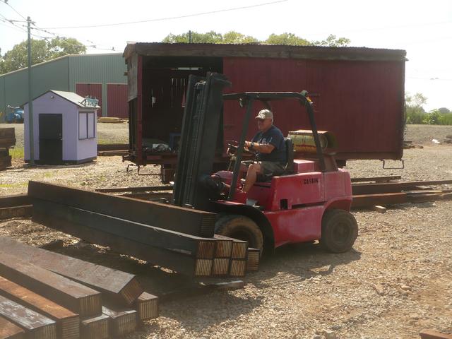
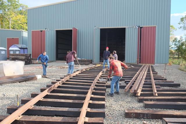
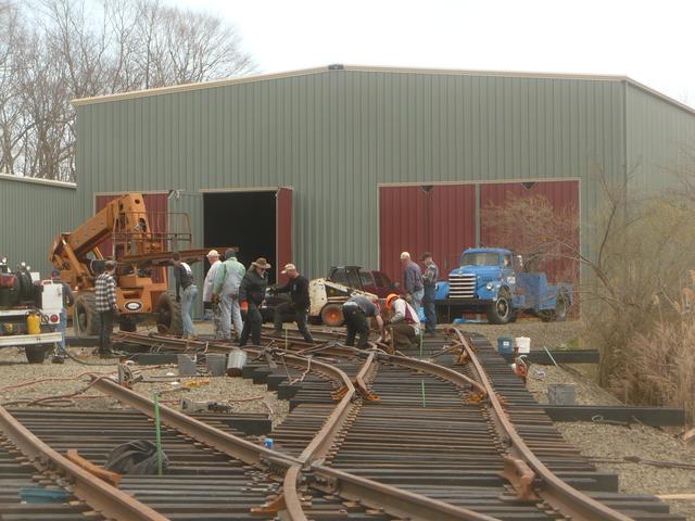
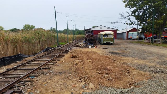
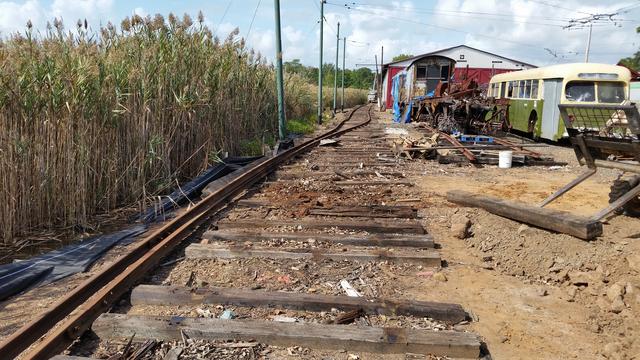
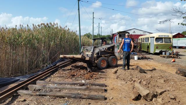
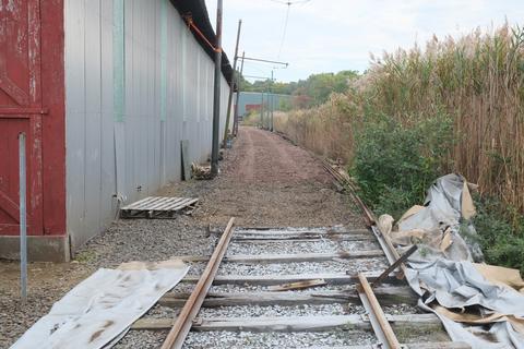
Mar 23-30:
An obstacle in the path of the track leading to the new barns was the pair
of temporary tracks containing parts storage boxcars. One such track was
extended to the east by about 18' and all the cars were moved up with a
payloader. Then one boxcar on the other track was moved out of the way
onto an isolated stretch of track. This boxcar, which is not part of the
museum's historic collection and is in poor condition, will be transferred
to a private collector soon.

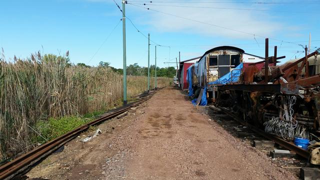
The view from the ramp looking back towards the main line. The back-guy
with its yellow safety guard will be relocated. The track, whose center line
is marked by the green stake, will turn left here and descend to meet the
new main line turnout.
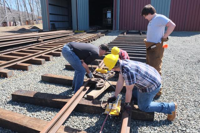
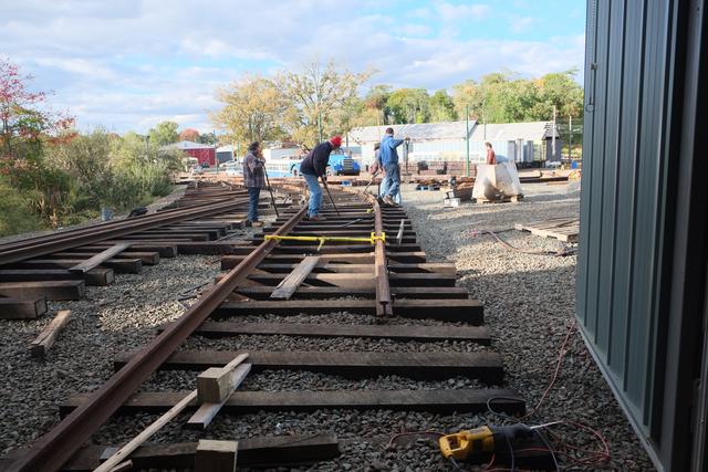
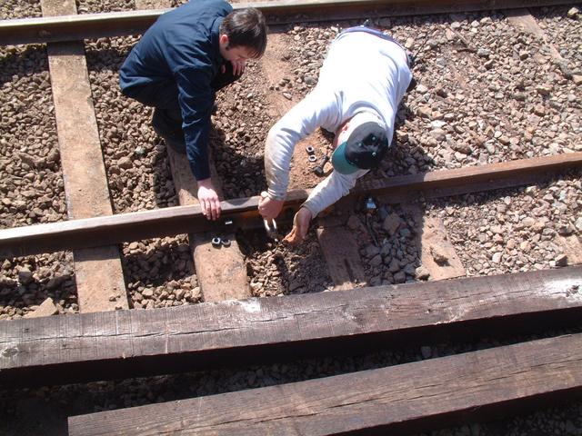
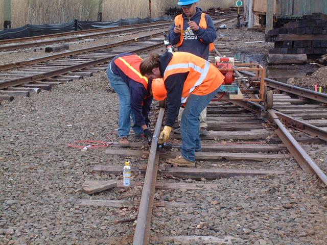
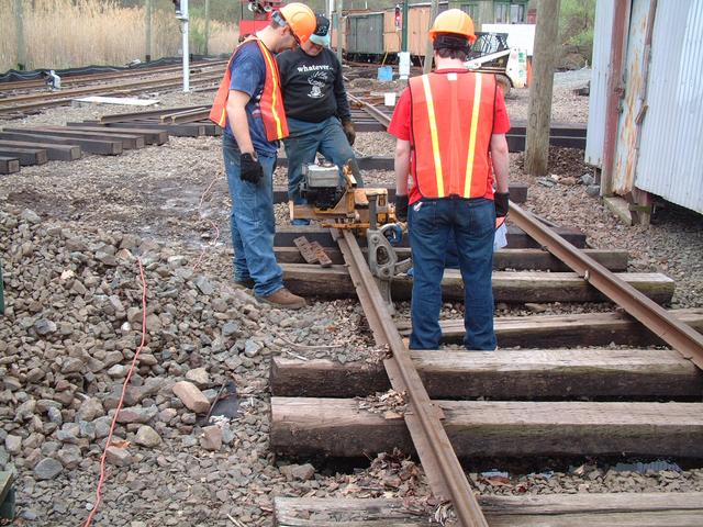
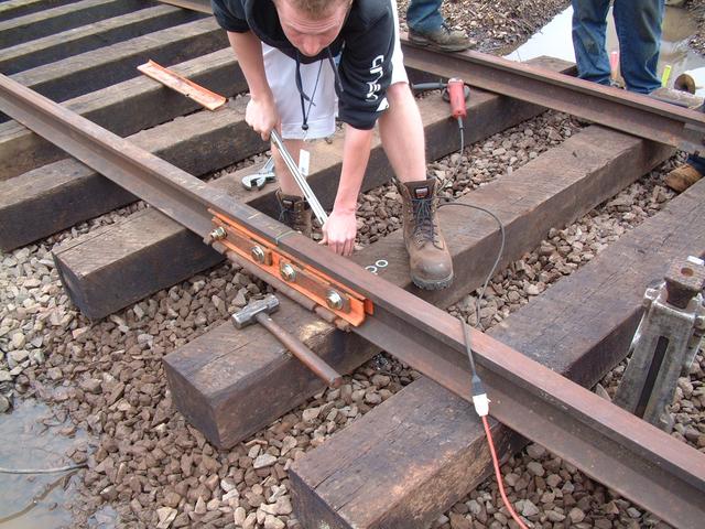
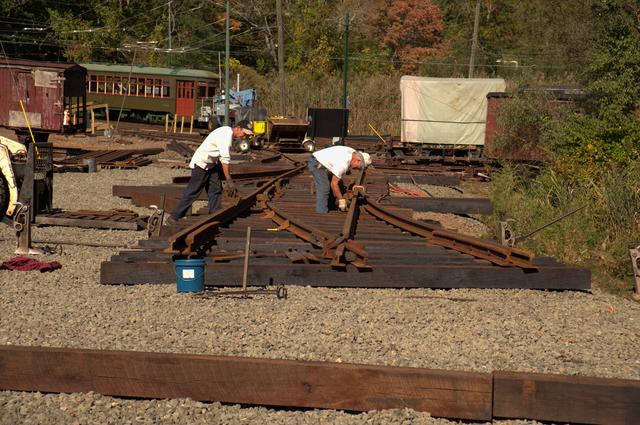
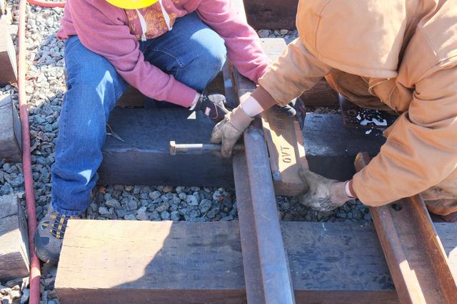
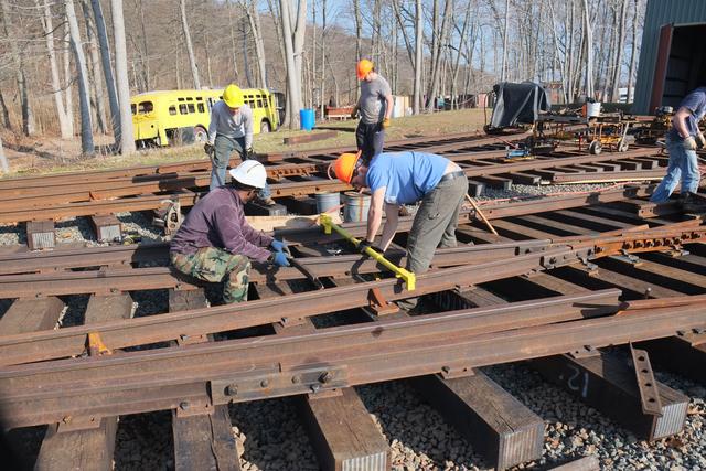
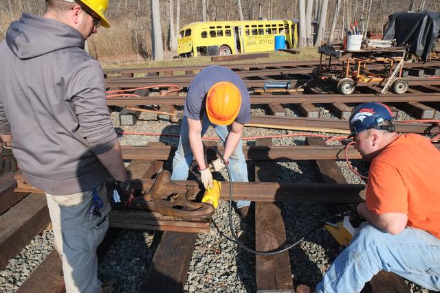
There are many components to a turnout. Here GWCC students install the
"heel block" which forms the pivot point for the switch.
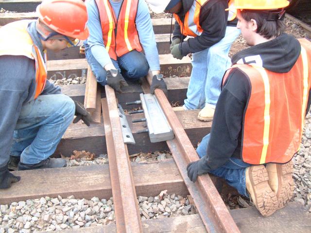
Both heel blocks are installed, and the diverging stock rail is being
gauged against the frog, as GWCC professor Larry I. inspects the work.
Work continues as the correct plates are installed under the rails and
spiked down. The switch points have now been connected up to the heel blocks,
and both closure rails are connected between the heel and the frog. The
rail on the left has been spiked to position so that it lines up with the
existing rails.
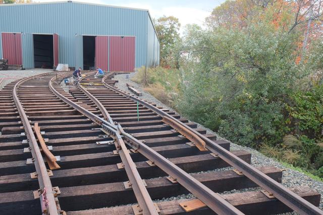
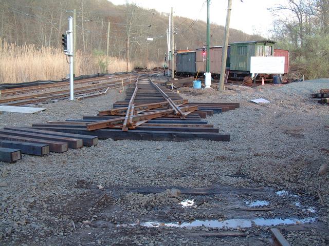
The turnout on March 30, view from the west and east ends. Heavy rains
earlier in the day meant working in muddy conditions.
The Bobcat brings a load of stone to begin tamping up the switch.
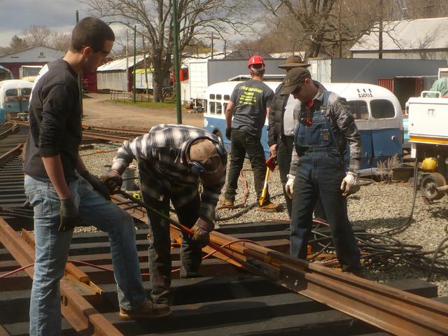
Main Line Turnout Open for Traffic
Apr 1-13, 2014:
The first new turnout in the Elevating the Collection project is now
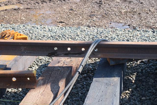
open for traffic! The turnout had been designed to coincide with one
existing joint in the main line, requiring the addition of three new joints.
Three lengths of 78NH rail were cut to exact length, drilled and installed.
This restored the continuity of the outbound main line track.
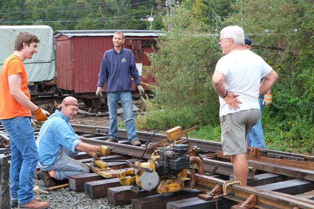
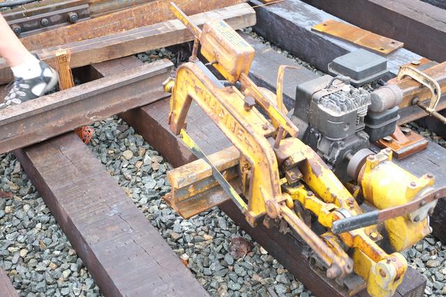
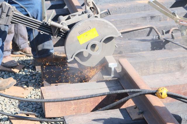
Above: using our somewhat antique gasoline-powered rail hacksaw to trim
a piece of rail to length. Below: Drilling the holes for the joint and
bolting up the joint bars.
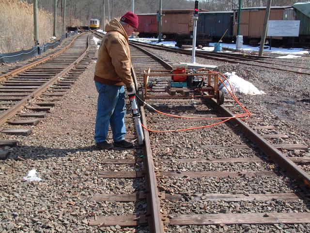
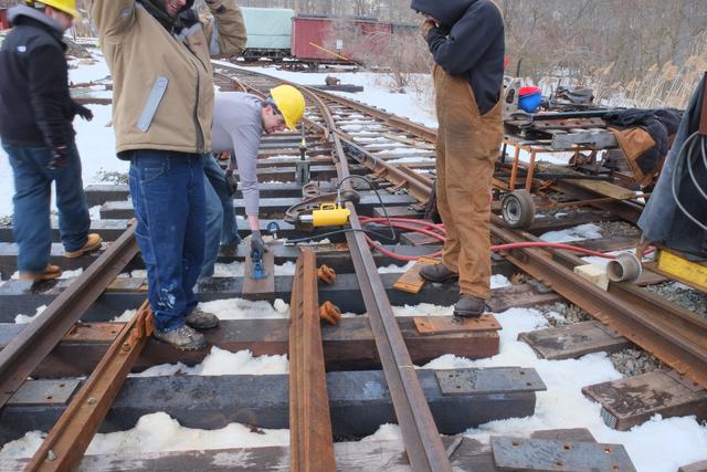
After the turnout had been entirely spiked and gauged (on the main line
track side only for now) it was placed in proper level. The yellow
spirit level board checks the cross-level. If one rail is higher than
the other, the track is jacked up and the pneumatic tamper is used to
tamp the tie firmly to hold the correct level.
For the record, the first ever trip over the new turnout was a test run
by this "car mover".
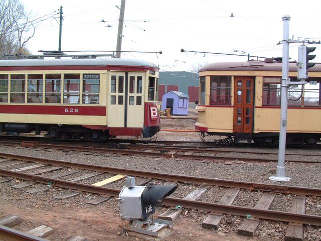
The turnout was tested with a number of cars in the collection, including
Third Ave 629.
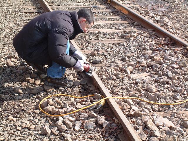
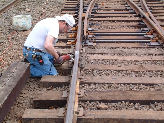
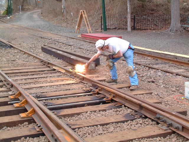
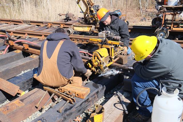
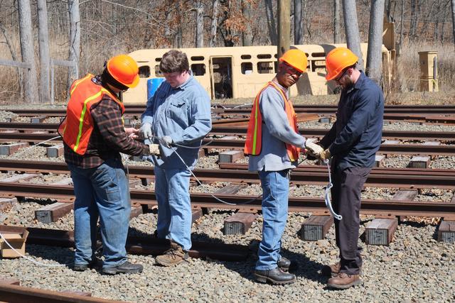
Meanwhile, it was time to restore the electrical continuity to the
main line rails. One of the rails is used to complete the traction power
circuit (the other is used for signaling) and needs to be bonded to
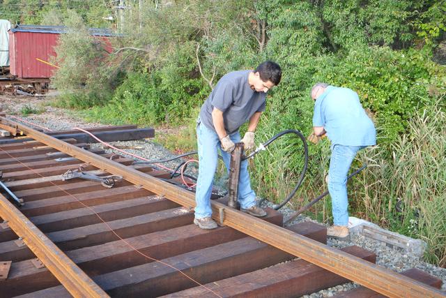
ensure proper grounding of the track. The process starts by grinding down
the side of the rail head smooth:
Then the bond is clamped to the rail with the bonding fixture and the
latter is charged with Thermite -- an incendiary mixture of different
metallic powders.
A special spark striker allows the operator to throw a spark from a safe
distance, setting off the Thermite charge which welds the bond to the
side of the rail.
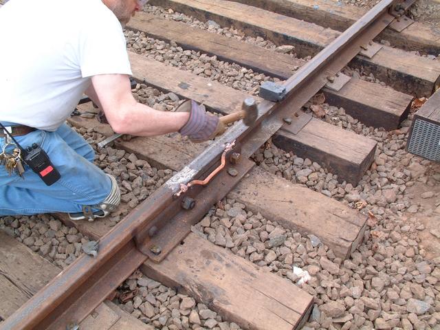
The excess metal is then peened out and the bond is ready for use.
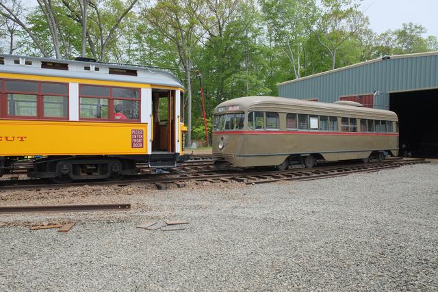
The next phase of the project will be to install a crossing of one
of the existing yard tracks. Since this will make two of our existing
barns inaccessible for several months, cars have been repositioned to
take this into account. Below car 629 tows car 2001. Its motors were
damaged during Irene and have been overhauled through the FEMA-subsidized
hurricane damage recovery program. It will soon have these motors
re-installed to return it to operational condition.
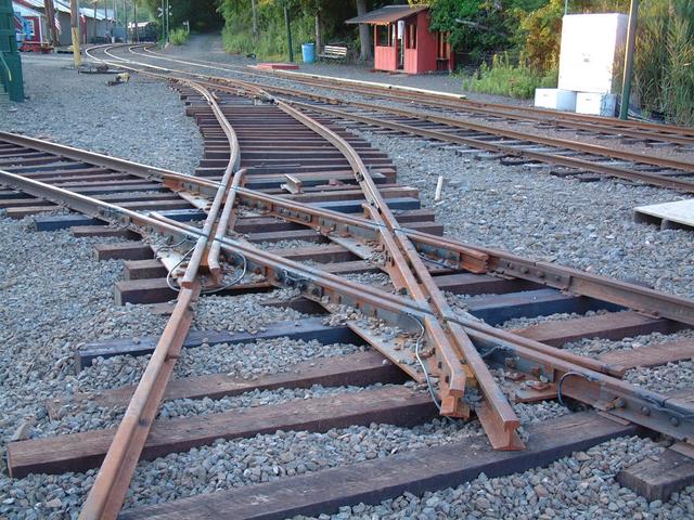
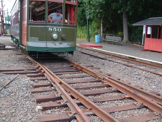
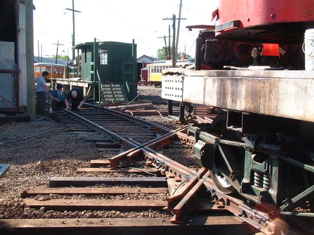
Crossing Installation Begins
Apr 14-29: Following the first mainline turnout installation in almost
40 years is the first track removal in almost as long! The lead to the
new buildings must cross the existing "Narragansett" siding track, which
was installed ca. 1960 and was named in honor of the company which donated
the material, the Narragansett Brewing Co. Narragansett track serves and
will continue to serve an important function at the museum: it provides
access to the high-level platform, Barn 1 and to the east end of the car shop.
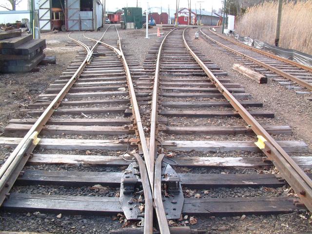
Above is the spring frog of Narragansett switch in the foreground. The track
on the left is Narragansett siding (the other track is the outbound main
track, with the new turnout in the distance). The next switch is a
single-point switch providing access to track 21. It was not possible
to retain this switch in the new track layout. Therefore the east end of
Barn 21 will be disconnected. Access is still available via the west end,
although it requires traversing barns 4 and 7. 21 track and the single-point
switch are being taken out. The rails of Narragansett siding will be
temporarily taken up, then re-installed once the new crossing is positioned.
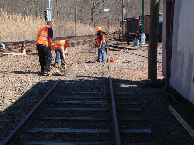
Removal began by digging out the ballast. Because this area has been used
from time to time as a vehicular pathway, the ballast was packed down hard.
For the record, the last use of 21 track was made by crane W-3 to pick
up rail which was stockpiled near Barn 2. Once the track was pulled up,
this rail would have become inaccessible.
With the ballast was removed it was possible to unspike and unbolt the rail.
Crane W-3 was then used to lift it and stockpile it for future re-use.
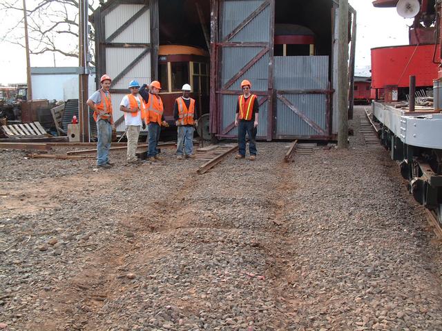
Gateway College students pose with the now disconnected 21 track.
Members' Day was held on Saturday, April 26, with a large number of cars
operating. To avoid potential logistical difficulties, Narragansett track
was left in place for one more day. But on Sunday the 27th, work began
on temporarily removing this track too.
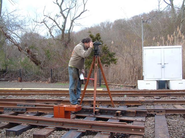
With the rail out of the way, an old-fashioned engineer's transit was used
to stake out the lines of the crossing. The plumb bob hangs over the
the point of the frog of the new turnout, which is a control point.
In our next update, we'll look at the crossing installation.
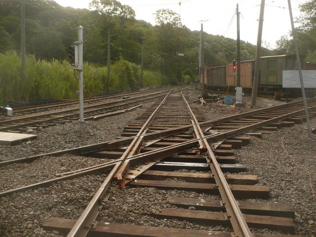
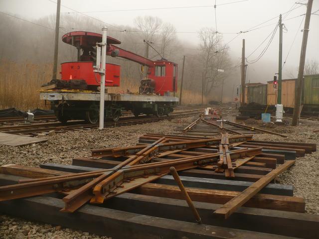
Narragansett Siding Reconstruction
Apr 27, 2014:
With Members' Day concluded, work began the next day to complete ripping
up "Narragansett" siding. Ties were then placed in the area of the new
crossing, and then the crossing itself was placed down in roughly the
correct spot. Work proceeded railroad east until all of the old siding
was removed up to the frog of Narragansett switch.
Above: Pulling out the 21 track switch. This single-point #4 switch has been
set aside for potential re-use elsewhere in the project. Below: The
crossing was manufactured in two pieces for shipping (otherwise, at 17 feet
across, it would have been too wide to ship). After the two pieces were
set down, it took a few hours to get everything lined up and reassembled.
The old Narragansett siding was a mixture of 60, 78 and 80 pound rails.
After removing the old rails, the old ties, which were in poor condition,
were removed with the Bobcat, which then distributed stone and new ties.
Next new (to us) lengths of 80 pound rail were distributed and placed in
rough position.
May 9, 2014:
The rails were cut to the correct length to fit between the crossing and
the existing track, and then drilled where needed so that the joints could be
made up.
There is a signal (17E) along Narragansett siding, so an insulated joint
had to be re-installed at that location:
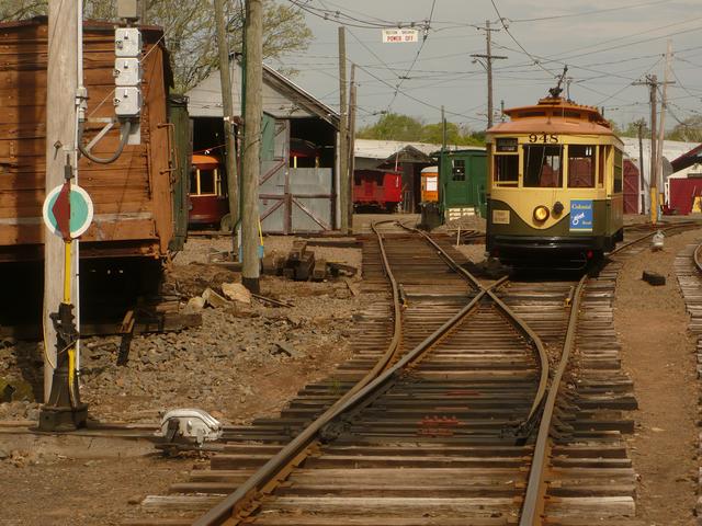
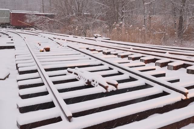
Car 948 passes the work area on May 13. All rails and ties are in place,
but nothing is spiked down yet.
Shortly thereafter, the rails were put into rough line and spiked
every 10 feet or so. This gave the track enough stability to allow
the stone hopper to traverse the track and spread ballast.
Meanwhile, back on the Island, spring has arrived, and Pasqualini
construction returned to perform the required erosion control seeding.
The stormwater detention swale is already filling in nicely with
grass that will help hold the soil together.
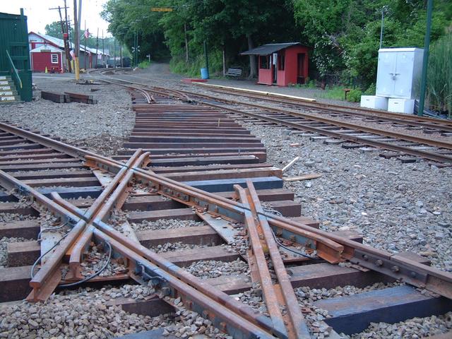
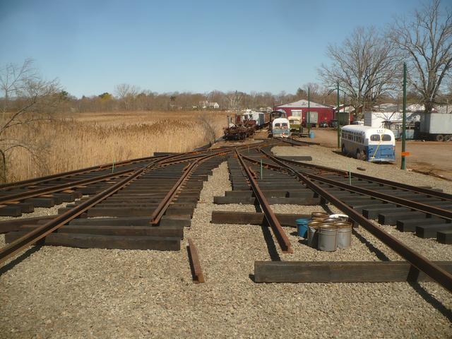
Narragansett Siding Re-Opens
June 22, 2014: For the past few weeks, museum volunteers were hard at
work finishing up work on Narragansett siding and the new crossing diamond.
The siding was declared open for all traffic on June 22, although it had
seen limited use with work equipment and high-level platform (rapid transit)
cars during the previous two weeks. This completes another important phase,
and concludes the portion of the trackwork project which interacts with the
existing railway.
Above: the official first trip through the crossing took place in late
May, with crane car W-3.
Since the last report, the entirety of the renovated Narragansett siding was
spiked down. Every tie from the frog of the existing Narragansett switch
to the east end of the high-level platform is "new" -- either a brand-new
tie or a high-quality relay tie. Additional ties were renewed in the area
of the platform.
Above we see spiking in progress. Once the rail was spiked down to all of
the ties, it was time to set the level. Using a modern laser level, the
proper grade was established from the crossing diamond, downhill in both
directions to meet the grade of the existing track. The newly-installed track
was then jacked up in small sections, guided by the laser, and the ballast
stone was tamped under the ties to hold the lift:
Above: tamping using hand-held pneumatic tampers. Below: the new crossing
is installed and pointing towards the Island.
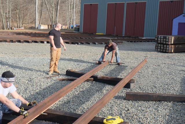
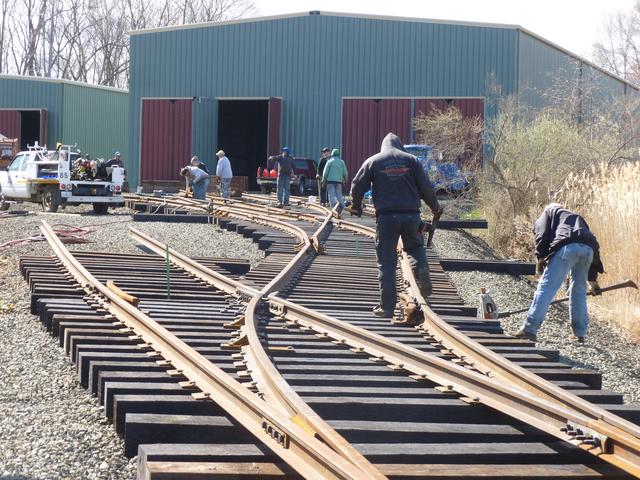
Creating the new track
July 4, 2014: Our attention now turns 100% on the new track
which leads us to the Island. One short 40' stretch connects the new
turnout (installed during the spring) with the new crossing, and contains
a slight curve. The first step was to stake out the alignment of this
track with surveying instruments and then distribute the ties guided by a
string stretched between the stakes:
New lengths of rail were placed into rough position:
To fabricate the required bend in the rails, the position of the curve
was measured and marked on each rail. A hydraulic rail bender was used
to put a small bend in the rail every foot. This large number of
small "kinks" forms a good approximation to a perfect arc, and is the way
that curves have traditionally been formed. The force exerted by the hydraulic
ram to form this particular bend, a 120' radius curve in 80AS rail, was
about 10 tons.
After a few bends are made, the radius is checked by using a geometric
principle known as "the middle ordinate of the arc." A string stretched
tightly from one end of the curve to the other will obviously take a shorter
path than the arc of the curve (the bent rail). The distance between the
string and rail at the mid-point has a specific and easily computed
mathematical relationship to the radius of curvature and the arc length. In
this manner the radius can be checked:
Moving up the Ladder
The next batch of 4 switches has been delivered. When installed, these
will give us access to 3 of the 4 tracks in new building 8, and the
beginning of the new loop track.
Above: Frogs, heel blocks and (below) frog guard rails have just arrived on the work site.
Between the new crossing and the first switch there is a stretch of about 40'
of straight track, followed by about 40' of curve to the right. The head
of the nail of this survey stake marks the exact position where this curve
will end, and the first switch will begin.
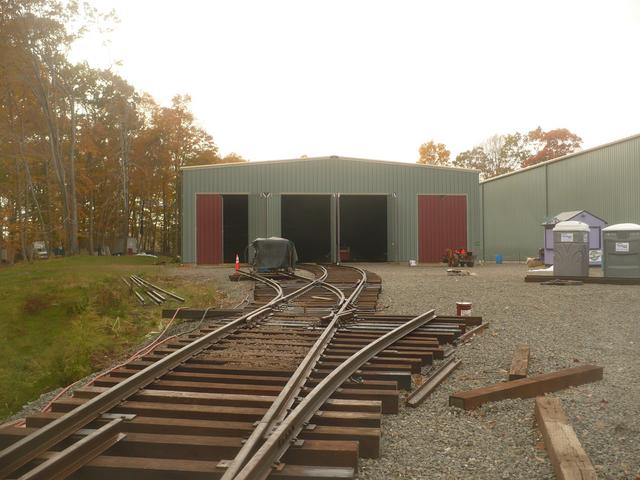
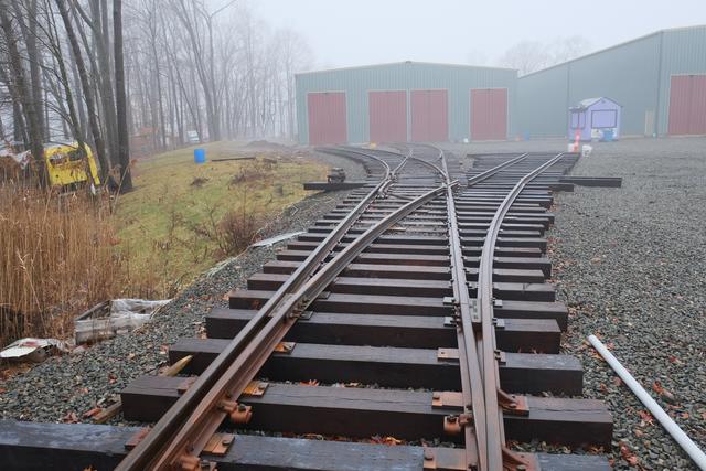
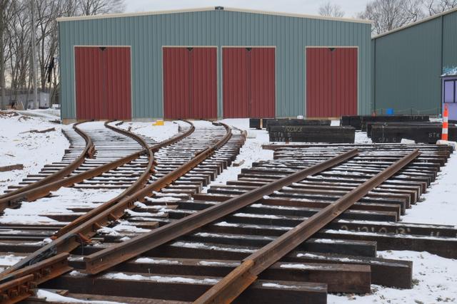
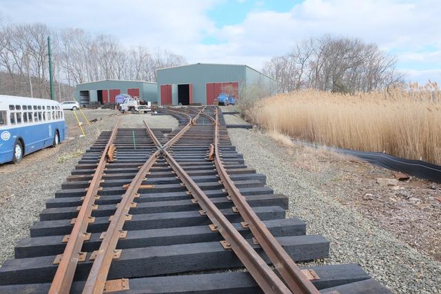
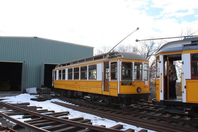
Looking railroad west at the re-opened Narragansett siding and the new
crossing track taking shape. Soon car 775 will be able to take the route
to the viewer's left and ascend to the Island.
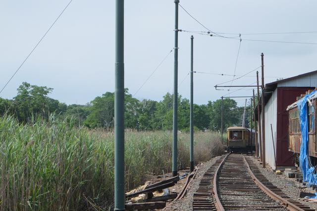
Up the Hill We Go!
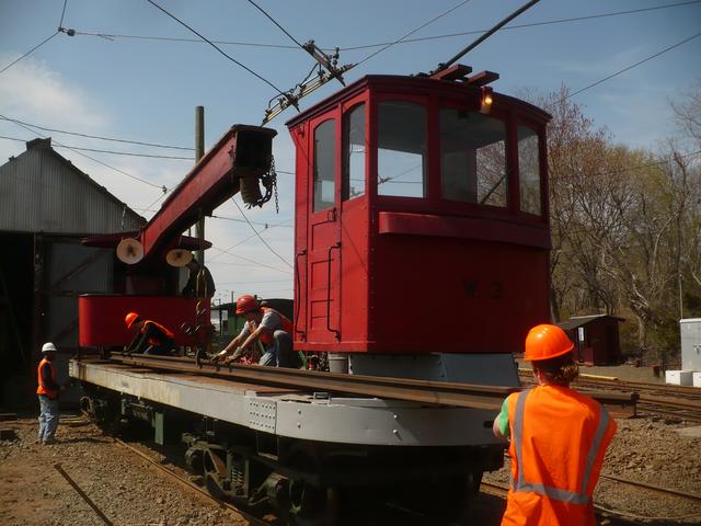
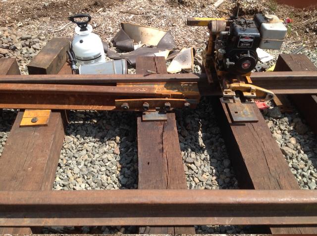
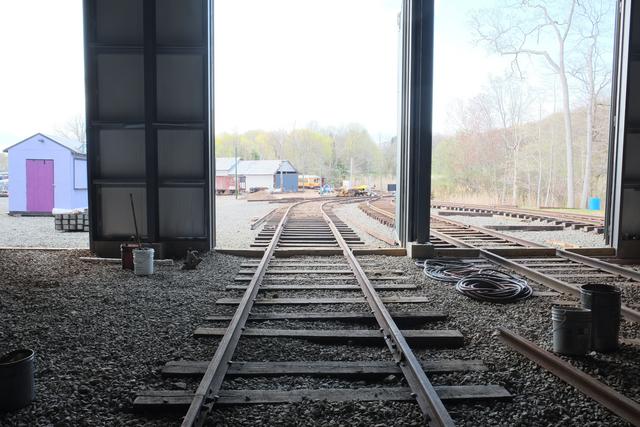
August 16, 2014: With the completion of the first 80' of track
beyond the crossing, shown in the last update, it was now possible to
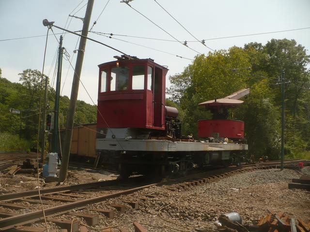
bring equipment onto the new lead. Below, crane W-3 is the first
car to operate over this trackage. Since the overhead wire is not up yet,
it was moved using a "stinger" connecting its pole to the live wire
via a long cable.
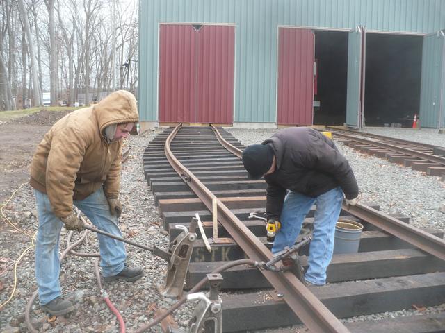
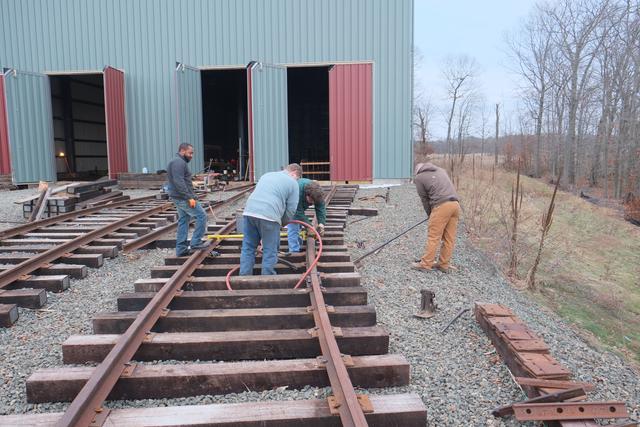
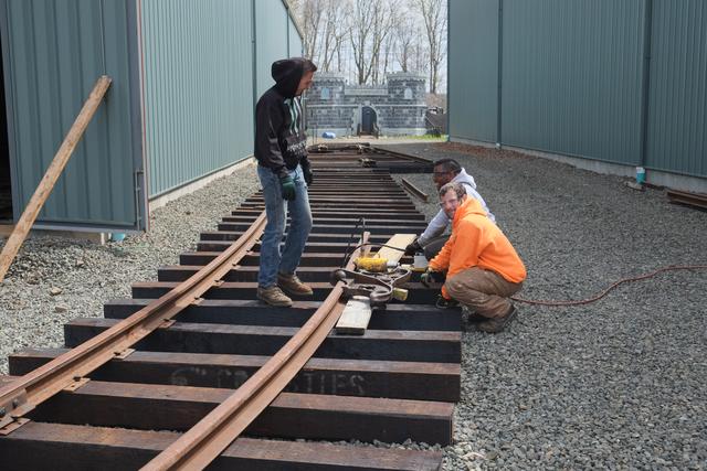
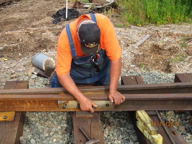
Working on Turnout 81-B
Turnouts are the most complicated and time-consuming of all track work
projects. Installation must proceed methodically with careful attention
to details and measurements, so that all of the geometrical constraints
are met and cars can track through without difficulty. Work begins at
the "point of switch" and proceeds to the "heel" of the switch.
Above, holes have just been drilled for the heel block casting.
Below, the heel block unit is assembled.
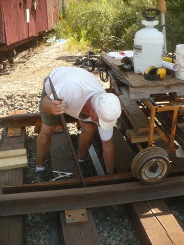
The rail bender is needed to curve the outside (stock) rail and one
of the closure rails to the required radius.
Once the turnout has been spiked to gauge between PS and HS, and the
point rails have been attached, the rods between the movable points
can be installed.
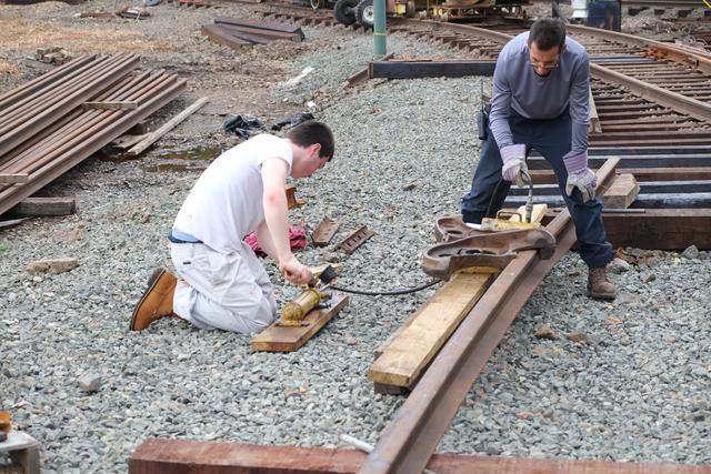
Spiking continues for the straight portion of the turnout, working towards
the frog. In the sequence below, two holes are pre-drilled through the
single-shoulder tie plate into the tie, the spikes are set easily with a
small hammer, and then driven down with the spike maul, or the pneumatic
hammer, while an assistant uses a lining bar and a fulcrum to keep the
tie seated securely against the rail.
The operation continues another day. The stake in the foreground is
used to control the rough alignment of the stock rail.
Sometimes the gauge is tight and hard to move by hand, so a pair of jacks
can be used to spread the rails prior to spiking.
Spiking of the straight closure rail approaches and then reaches the frog.

At the frog, special tie plates known as "hook-twins" are used, because
regular plates won't fit in the close spaces.
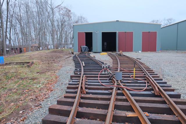
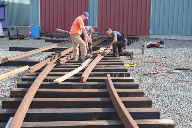
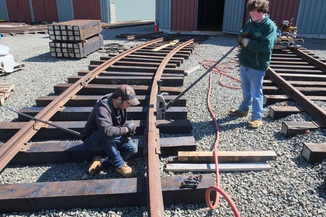
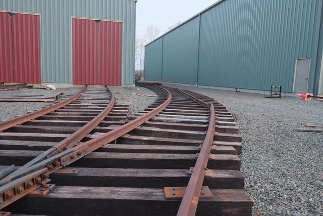
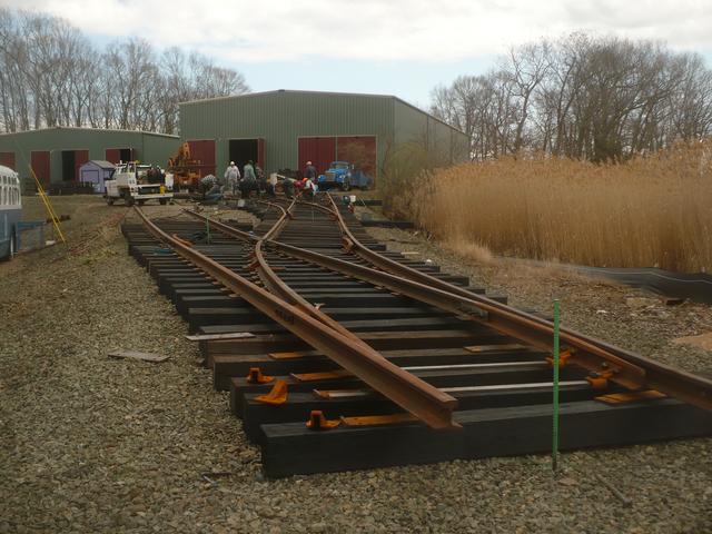
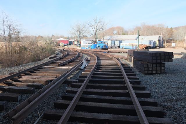
On to Turnout 81-85
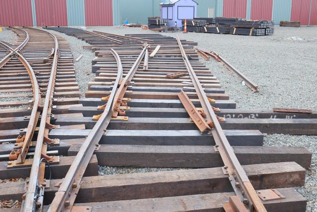
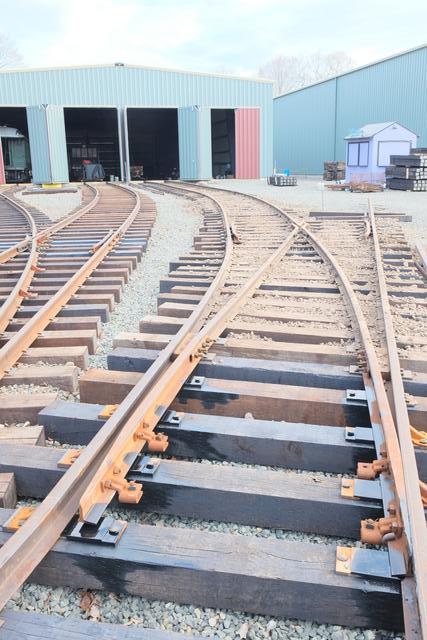
September 2014: As work on 81-B reached completion, the next
turnout, 81-85, was begun. Ties were brought into rough position,
spaced and aligned:
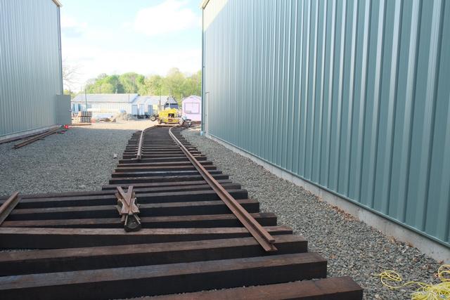
The view below shows turnout 81-B completed, on the straight side.
The diverging side will be the start of the Burch Memorial Loop.
In the foreground, installation of the brace plates for switch 81-85
has been completed, along with one rail of the 15' curved connecting
track between 81-B and 81-85.

At the far end of 81-85, the frog has been placed roughly into position
and attached to the straight stock rail. Spiking of the straight side
between the heel of the switch and the frog is underway. The orange
stringline, stretched between stakes, guides the centerline alignment.
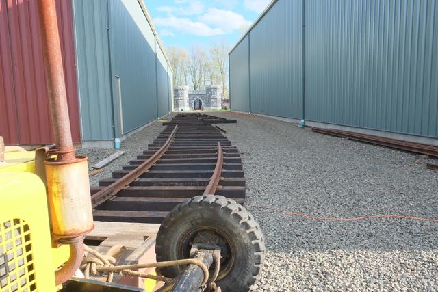
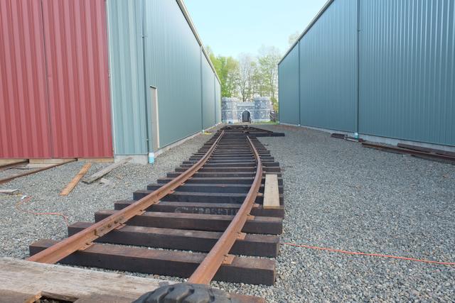
The track curving to the viewer's left will lead to turnout 83-85,
while the straight track to the right begins turnout 81-82.
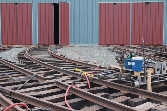
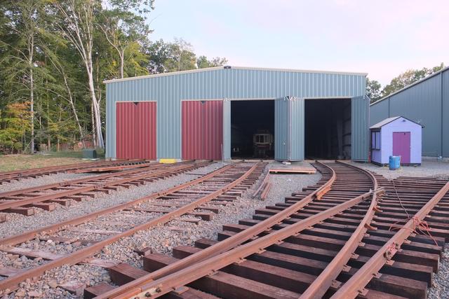
View from points of 81-B turnout, with Building 8 and Haunted Isle
decorations in the distance:
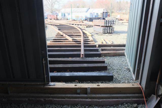
Building 8 Connected !
During the month of October, a milestone was reached with the connection
of 82 track to the building 8 ladder, thus allowing cars to reach the inside
of the building for the first time!
Early October 2014: A small crew of volunteers from other trolley
museums visited for a day and helped us with the interconnection of 81-B
and 81-85 switches, bending and cutting the remaining short length of rail:
Spiking continued through the 81-85 switch, working up to the frog:
Mid-October: The rails and ties were laid out for 81-82, the
last turnout in the ladder needed to reach 81 and 82 tracks. The stringline
guides the center-line of the track:
After spiking of 81-82 was completed, work had to wait a few days until
the Haunted Isle event was concluded, since they were set up in the path
of the oncoming track! During this period the rails for the 82 track
connecting curve were pre-bent:
Late October: Ties and rail were now placed for the connecting
curve. The rail bending was completed and the rails were installed into
the building.
Rails are in the door:
All that remained was about 30' inside the building, where the rails
steps down from 80 to 60 pound. Progress on this was made during
"Work Party Day" on Nov 1:
Putting the finishing touches on the track just outside the building:
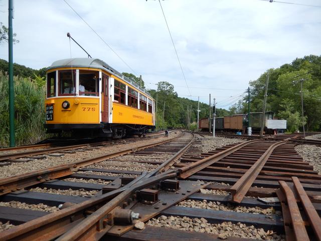
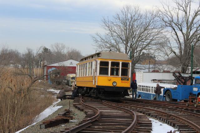
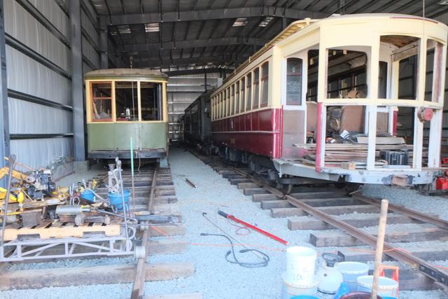
First Car In!
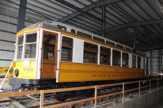
November 8, 2014 was the day of the museum's annual membership
meeting. Car 775 was selected for the ceremony. This car was built
in 1904 and spent much of its career running on the museum's line (when
it was part of the Connecticut Company's network). It was restored at
the museum and is one of the regularly operating cars.
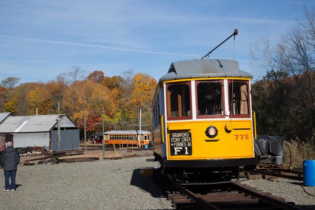
Above: Car 775 waits outside as the crowd gathers. Below: The trolley car
enters the building for the first time.
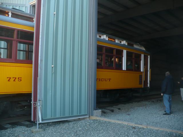
There is no overhead wire on the new tracks yet. A special "extension cord"
with a "stinger" was used to bring the trolley power to the pole of car 775.
This allowed it to run under its own power.
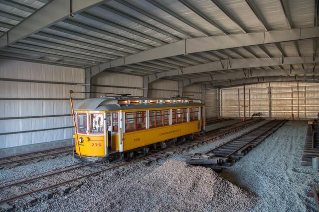
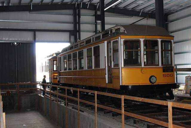
This was only a ceremony, however. 775 will be used during the busy
end-of-year season. The next day, the car was run out of the building
and back into Barn 3. In the event of a flood, the car can be run back
to the safety of higher ground. With the track temporarily empty,
Car 500, the "pride of the fleet," was towed to the back of 82 track.
This car has not received repairs from the Sandy and Irene floods and so
it could not operate under its own power.
81 Track is Done
December, 2014:
By early December, track 81 was connected but not yet lined or spiked.
A few temporary spikes were quickly put in so that we could make our
first car move on this track: Horsecar 76, our latest addition to the
collection and the oldest (in fact, the oldest preserved streetcar in
the world!) Because this car is very light, hardly heavier than a track
tools cart, it was easily pushed up the grade, around the curves and into
the building:
Spiking of 81 was completed a few weeks later:
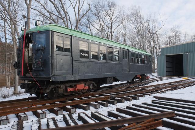
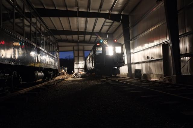
Next up was the widest, longest and heaviest car in our collection which
is currently operable: New York City R-9 class subway car 1689. It was used
to check clearances and the ability to negotiate the reverse ("S-") curve
leading to 81. It was successfully run into the building, where it will
spend the winter.
Track 83 layout begins
Early January, 2015:
Next up is turnout 83-85, which will give access to track 83. The first
step was to bring up 24 switch timbers and lay them out according to the plan:
Two rails were brought up from the pile and placed into rough position.
They will need to be bent and then installed, and will form the stock rails
of 83-85 turnout:

A delivery of 250 ties needed for the connection to tracks 83, 84 and 85
was received at Sprague Station on a snowy day:
Crane car W-3 brought the ties up to the yard ladder were they were staged
in bundles near where they will be used:
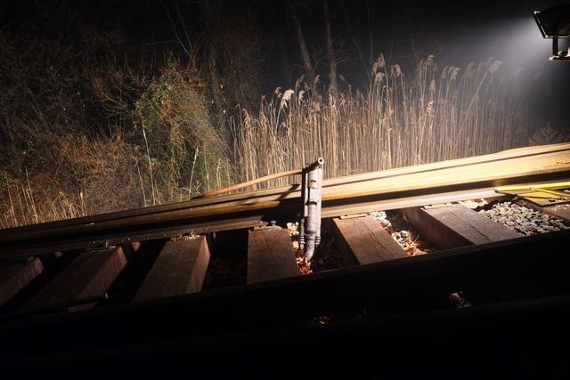
Daylight is short at this time of the year, which has meant some night work.
Here the pneumatic spike driver is spotlighted on a foggy night:
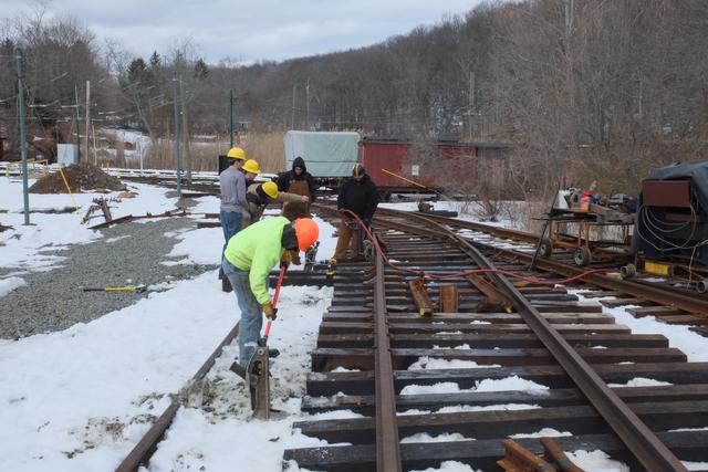
Snow finally gone, outdoor work resumes
March 15, 2015:
After being snowed in for almost 2 months, the ground was finally visible
enough to resume work on the 83-85 turnout. The straight closure rail was
spiked to line:
Pre-drilling and spiking with the air hammer:
The "stock" bend was made in the diverging stock rail. This single
bend matches the angle of the switch points ... about 4 degrees, and is
done by repeated trial until the point fits correctly and is in the correct
gauge:
March 20-22, 2015: You've got to be kidding! The first official day
of Spring greeted us with a 3-5" snowfall :( Thankfully it melted and
a few days later work continued. Here the diverging stock rail is being
spiked to gauge. The rail braces are hammered into place for a snug fit:
The spikes are driven most of the way with the air hammer, but the shape of
the plate doesn't allow the hammer to reach the bottom.
So this part has to be finished with the old-fashioned maul.
Next up is making the long bend in the curved stock rail. The rail is
bent every foot with the hydraulic bender:
March 24, 2015:
Our final delivery of switches and frogs arrived and was quickly
unloaded by crane W-3 and transported to the Island area. These 6
turnouts will complete tracks 84, 85, 90, 91, 92, 93, 94 and the
new loop.
April 1-3:
Inside Building 8, stone has been spread over the completed track
And ties have been laid out in anticipation of connecting this track
to turnout 83-85.
Back at the turnout, holes are drilled in the stock rail and closure rail
for the heel block:
The heel block is assembled, joining the stock rail, closure rail and
point rail:
Additional lengths of rail are positioned, in this case by hand using
rail tongs. These GWCC students are standing in what will eventually
become the 84-85 turnout.
View of 83-85 turnout with straight closure rail and frog, from
both directions:
Building 9 Ladder Constructed!
April 19-24, 2015:
Many thanks to a multi-museum team of experienced track volunteers on
a mission of charity, who visited during the week prior to Members' Day
and accomplished what seemed almost impossible: 4 turnouts constructed
in 4 days!
These volunteers came mostly from the Illinois Railway Museum (IRM), the
largest railway museum in the United States, along with Pennsylvania Trolley
Museum, Minnesota Transportation Museum, and our own Shore Line Trolley Museum
volunteers. The job began with staking out the location of the turnouts
using surveying instruments:
Ties were distributed to the bare site by Bobcat and then positioned by hand:
Using the stakes and a stringline, the ties were spaced and lined up:
The lie layout is complete,
and the first piece of rail is brought into position. We are grateful to
A&G Construction of East Haven for the use of their Lull telescoping forklift,
which greatly eased material handling.
The two stock rails of what will become turnout B-94, the throat of the
building 9 ladder and the beginning of the new Birch Memorial Loop.
IRM brought their hy-rail track department truck, loaded with enough hand and
power tools to keep the entire crew occupied!
These tools included this hydraulically-powered abrasive rail saw, which made
much quicker and easier cuts than our pre-historic reciprocating hacksaw
machine!
Another useful machine was this hydraulic rail drill. It was much lighter
and easier to position accurately than the museum's drill:
With this, the first of many holes were drilled, for the heel
blocks of B-94 turnout.
Another handy device was this spike-setter, allowing a helper to hold the
spike while it is set by the air hammer. After a few pops, the spike setter
is withdrawn and the air hammer finished the job. This was a lot faster than
pre-drilling and/or pre-setting the spikes with a maul.
The straight side of B-94 turnout is done, only a few hours elapsed!
Further up the ladder, the heel block of 93-94 turnout is being installed
as work continues on B-94 spiking the guard rail on the diverging side.
Students in our Gateway Community College Railroad Engineering Technology
internship program got valuable experience working with volunteers from
other museums, several of whom are track professionals. Here they are setting
the gauge wider than usual on the diverging side through the frog, to allow
proper guarding action with our mixed wheel profiles. An IRM volunteer
demonstrates the use of their gauge pusher, which is quicker than ours but
requires a helper.
On the third day of the project, turnouts B-94 (immediate foreground) and
90-94 are done, as work progresses on 90-92 and 93-94.
GWCC students make up the heel joints of 93-94 and 90-92:

Now we're up to the frog of 93-94, as it is lined up and bolted in.
The job is almost done, with just a few more finishing touches:
By Members' Day, April 25, 2015, museum supporters could see the fruits of
their donation dollars. These four turnouts are complete!
There is still more work to be done before Building 9 is connected. This
ladder must be cut-in to the existing "run-around" track behind Barn 6, and
one more turnout (90-91) must be constructed.
Meanwhile, back at Building 8, Track 83 connected!
Apr 22 - May 15, 2015
Not to be outshined by its neighbor, building 8 saw another milestone reached
with the completion of turnout 83-85 and the connection of Track 83. Below,
the curved closure rail is installed and spiked:
With the turnout done, out came the rail bender to make the connecting
curve to 83 track:
Following by spiking:
As we get to the tangent and the connection to the track inside the building,
a string is used to line it in:
The outside rail is complete as the inside rail is bent and spiked to
gauge:
Looking out from 83 track down the ladder:
and back in the opposite direction:
The "compromise" joint between the 80AS rail outside and the 60AS rail
in the building:
Levelling and tamping the track inside the building:
Car 1001 is the first occupant of 83 track, where it will be stored awaiting
flood damage repair of its control system and re-installation of the
overhauled traction motors. Car 775 does the towing:
Building 8 now completely connected!
May-Sep 2015:
It was a long, hot and humid summer in which Track 84, the last of
the four tracks inside Building 8, was completed. To access this track,
turnout 84-85, the last of the Building 8 ladder, was constructed:
Making up the heel block on the 84-85 turnout.
Two views looking back towards the mainline and ahead towards track 84
with the frog in place and straight side of the turnout spiked.
In this view, the next length of the curved stock rail has been made
up and it, along with a curved closure rail, have been bent to radius
and spiked to gauge. The turnout is now almost complete and all
that remains is the connection into Building 8.
The connecting track has been bent and spiked, and joined to the track
inside the building, which was partially built during the winter of 2015.
The track has been placed in service but full use is pending stone delivery,
levelling and tamping.
Run-around connection begins
Sep - Oct 2015
the turnouts for tracks 92-94 in the Building 9 ladder were built in
Spring 2015. Now that the daily operations season has ended, cars were
moved to clear the "run-around" track next to Barn 6.
Above: The run-around track is completely empty. Cars that were being
stored here have been moved temporarily to other spots in the yard.
Below: This track was in poor condition since it was only used to
store inoperative equipment. It will be replaced. The first step
is un-spiking the old 60-pound rails:
Above: The rails are all un-spiked and are moved to one side to
facilitate tie removal. Below: Tie removal in progress
After the ties were cleared, stone has been spread to bring up low spots:
Grading is now complete, view from B-94 turnout looking back towards run-around
and second view from far end of run-around track looking towards Barn 9
lead.
Building 9 connected via rebuilt run-around track
Nov-Dec 2015:
Building 9, track 93, is now connected to the railway via the completely
rebuilt run-around track. Although no cars in the collection are yet being
stored in the building, they will be soon after ballasting and levelling
is complete.
During November, the run-around track was being spiked:
At the railroad west end of the rebuilt run-around track, the new 80 pound
rail joins the existing 70 pound rail of the Barn 6 ladder.
Completed run-around track alongside Barn 6, looking east:
The run-around track is being connected to the head of the building
9 ladder, the B-94 turnout:
The next week, track is connected and flatcar has been run
through to deliver supplies.
View from 93 track looking railroad west down the ladder, and
looking east towards Building 9.
Dec 2015:
While ballasting is in progress, tie layout and bending of the
rail for 92 track has begun:
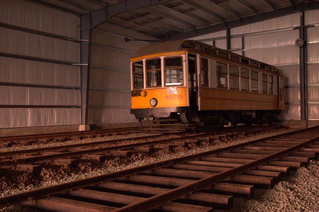
Track 93 in Service
Jan/Feb 2016:
Another project milestone was quietly observed as the calendar turned
to Feb, 2016, as car 500 was towed into 93 track. Its motors were
recently pulled as part of the ongoing flood recovery program, and now
it will be stored safely in Building 9 until the motors return from
the overhaul shop and it is time to complete the repairs.
Leading up to this moment, track 93 first had to be entirely completed
within the building. Since Fall 2015, this track has been used to store
the track tool cart, compressor and other light equipment. By late
December, with work progressing by floodlight inside the dark building,
this progress photo was taken from the front of the track looking towards
the back of the building. The track tool cart is in the foreground and
a lining bar protrudes upward:
A week or so later, the track was complete except for the last 15 feet,
which was finished with some "drops" (cut-off short lengths) right
after this photo was taken (from the back looking r.r. west, with future
pit track 94 on the left)
After ballast was spread over the completely-spiked track, these students
who just began their Gateway Community College internship are putting the
track in proper level (the yellow tool checks the cross-level, plus a laser
level for end-to-end level) and tamping the ballast by hand.
Here comes 500 climbing the steep grade as it passes through
93-94 switch:
To be honest, 500 wasn't motoring itself, despite the pole seemingly
being up. For one thing, there is no overhead wire here yet, and
500's motors are not in it. Car 775 is performing the towing and
is powered by a "stinger".
500 Enters 93 track.
View from other direction, 500 alongside future pit.
Construction of 91/92 tracks
Snowpack is impeding outside track work but work inside Building 9
continues. Below, 92 track is being spiked, with 91 track in the background
ready for spiking.
Track 85 nears completion, tracks 91 and 92 in service
Summer 2016: The next part of placing track 85 in service was
lining up and spiking the point-and-mate (or "single-point") switch,
which forms one end of a crossover between 85 and 90 tracks.
Only the straight side of this switch is being completed at this time.
Below we see the No. 4 frog which has just been connected to the straight
rail on either side. Hook-twin plates are being positioned to hold
the frog.

These are the point (on the left) and mate units. At the time of this photo,
they were not connected or spiked yet. This switch was "free" in that it
was taken out when 21 track was removed from service in 2014.
A few weeks later, the frog, point and mate are all spiked down with
hook-twin plates.
In early July, this was the scene in Building 9. Car 500 is almost invisible
in the dark corner of 93 track. 27 and 3662 are on track 92, and 91 is
complete and ready for cars. Track tools are stored on the rolling cart
in the foreground.
A few days later, switching moves were underway to populate these tracks.
Below car 1403 is being pushed by 6688 along the run-around track, next to
Barn 6, which leads to new Building 9.
And here is 1403 on track 91, with 2431 on track 92. Behind 1403 on track
91 (not visible) are 1403 and 1972. These un-restored cars
were all operable pre-Irene, and are being stored here to protect them from
the possibility of additional flood damage until they are repaired.
Emergency plan invoked for TS Hermine
Sep 3, 2016: With a tropical storm warning posted for our
area and predictions of moderate to major coastal flooding, the museum
invoked its emergency plan. Operations were suspended and cars were moved
to higher ground. There is now more than enough track space out of the flood
plain, and almost all of the operable cars were housed indoors too.
As it turned out, the storm stayed further out to sea, and there was no
flooding at all in our area.
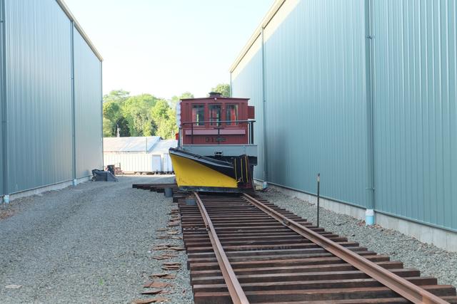
Below, cars 850 and 948 are on tracks 82 and 83, with 3152 in the "alley"
on 85 track.
View from the other direction with 3152 on track 85.
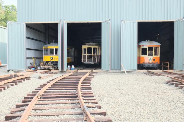
Building 9 is full of cars on tracks 91, 92 and 93. We see cars 2350,
2431 and 357, respectively. Construction is underway on track 94 (pit track)
but it was not ready to accept cars yet.
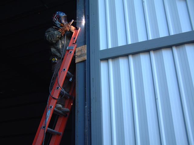
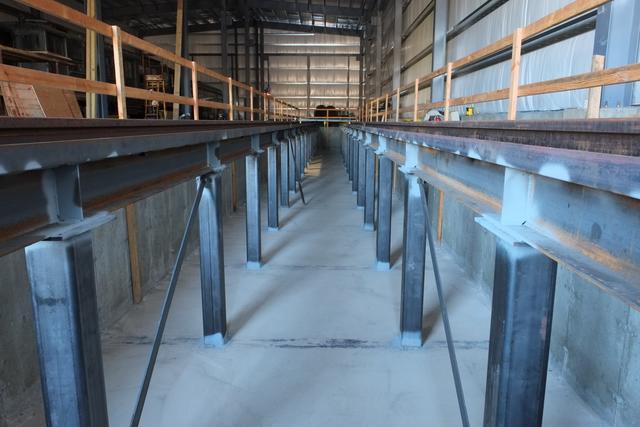
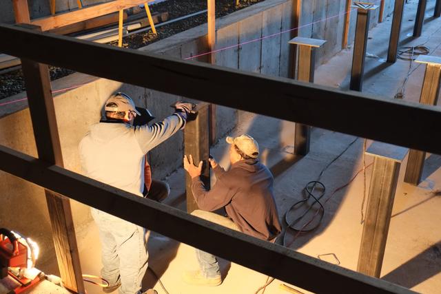
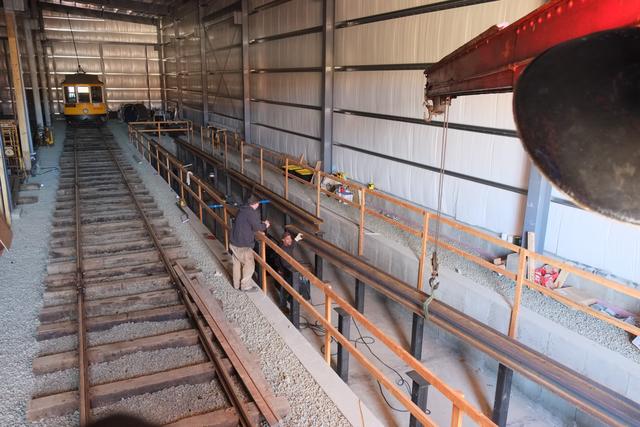
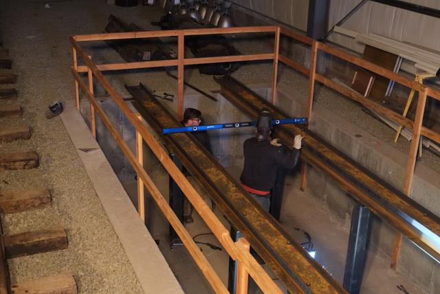
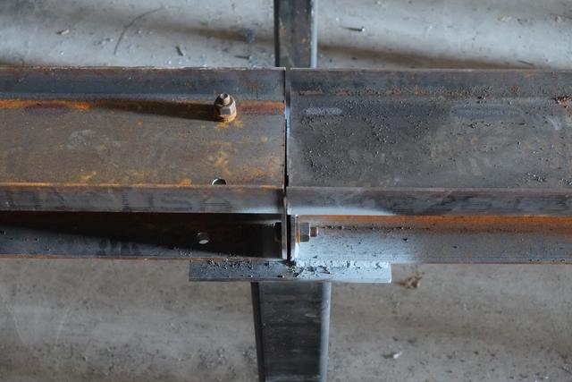
Pit track construction begins
Sep 18, 2016: Construction of track 94, the pit track, has
just begun. In the photo below, some of the columns have been delivered
and welded down to the support beams embedded in the concrete floor slab
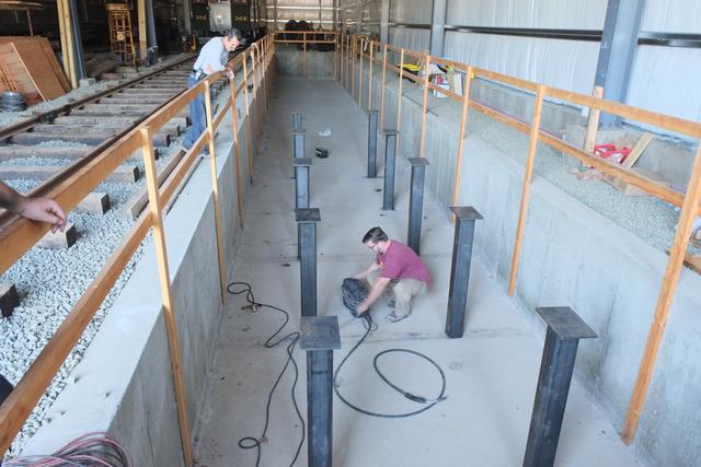
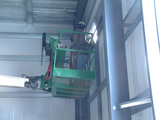
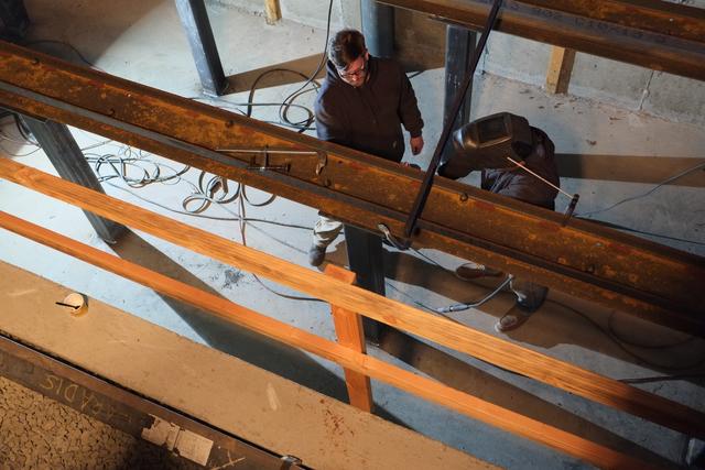
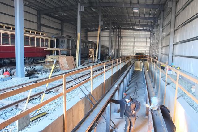
In mid-October, all of the columns were set, lined and plumbed. Below
workers are using string lines to line up the columns near the back end of
the pit. Note crane car W-3 on the adjacent Track 93. It was used to
deliver materials.
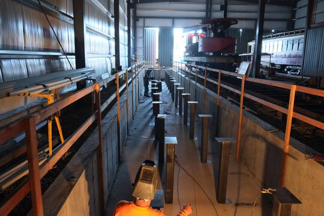
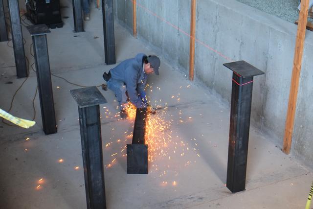
Each column was carefully plumbed and then tack-welded. The steel I-beam
embedded in the concrete floor was first prepared by grinding in the area
of the column to get clean metal.
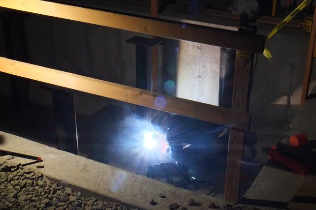
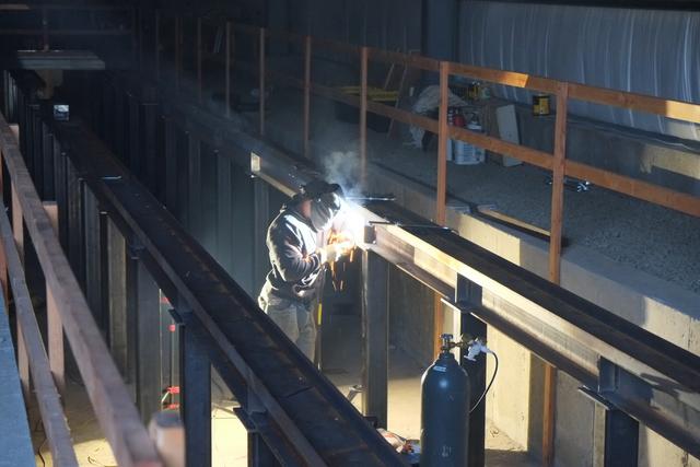
After all of the columns were set, the process of making the final weld
seams at the bottom of each column began:
Line Poles Being Set
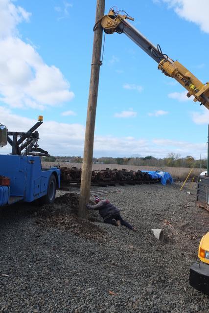
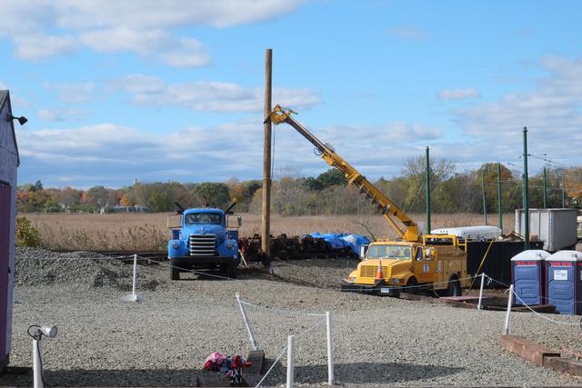
Late Oct, 2016: A utility pole contractor has begun setting
the line poles, the first step in getting live trolley wire over all
these new tracks. Here a boom-mounted auger is digging a hole 6-7'
deep through the embankment. The location is near the future new loop track
on the building 9 side of the yard.
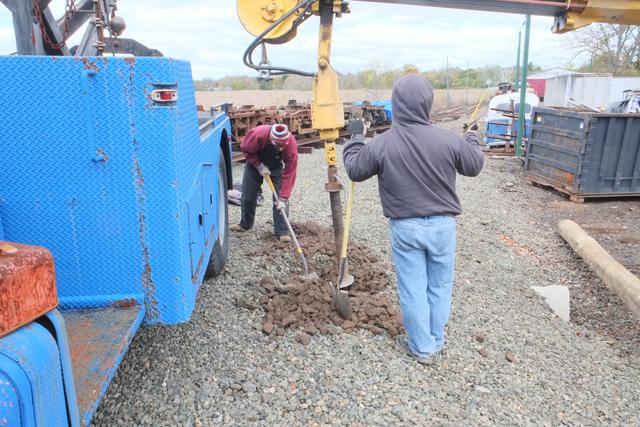
Once the hole is dug and the bottom cleaned out with special shovels,
the boom truck picks up the new line pole and sets it into the hole.
This tool, a "Peavey" pick pole, spins the pole so the branding mark
is facing a consistent direction. It doesn't make any mechanical
difference but it does make for a neat looking job.
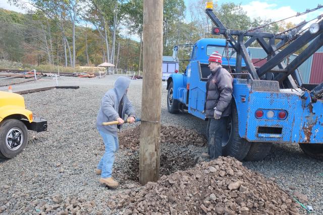
The boom truck detached from the pole shortly after this photo was taken,
after the hole was filled and tamped.
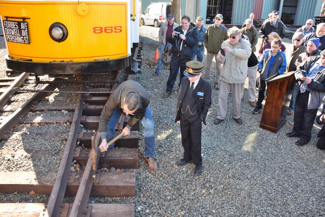
Driving the Golden Spike!
Nov 12, 2016:
Governor Malloy was our guest at the 2016 Annual Meeting. In a morning
ceremony, he drove a symbolic golden spike. With a crowd of museum members
and supporters looking on, and with a few perfect hits of the spike maul,
the Governor set down the spike on the 84/85 track lead. Situated around
him were cars 865 and 316, both of which have recently been repaired
after hurricane flood damage.
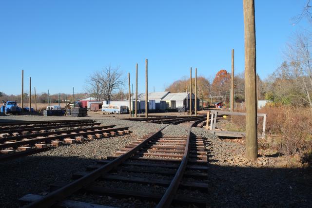
18 Line Poles Set
Nov-Dec 2016:
Line pole setting by a professional contractor continued through
November and into December. 18 of the 24 total poles have now been
set. With colder weather coming in, this will probably be it for line
work until the spring.
Above: setting pole E-5 on the north side of the approach ramp to
building 8. Below, view from track 81 with a succession of line poles
leading back to the mainline. Soon span wires and trolley wire will
be suspended from these.
Looking the other way. The area in the foreground will become the
Donor's Recognition Brick Area as soon as the loop track through here
is completed. That track will curve off to the right, passing between
the pair of poles.
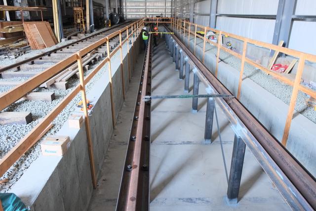
Pit structural work complete
December 2016: Our welding contractor has completed the structure
which will support the pit track. The next phase will be to install
the rails and then track 94 can be opened.
Below: Using crane car W-3 to set one of the span beam sections:
The level in both directions is checked prior to welding down the beams.
Welding the web stiffeners at each point of column support reaction.
Almost all of the structure is welded, but one section is bolted so that
it can be removed to access equipment on cars that might straddle the line
of the rail (such as air compressors and grid banks).
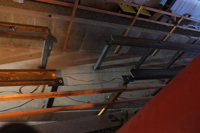
Completed pit structure:
Pit and track 94 complete
Mar 2017: With the help of our annual Gateway Community College
internship students, work on track 94 is now done and the track, including
the pit, is open for business!
Above: Installation of rail hold-down clips is at the mid-way point
in this early March view. The rail is being put into proper gauge
and then the hold-down bolts are tightened.
Above: The last 60' of the
pit track, back on solid ground. Track is being spiked with the pneumatic
spike driver. Below: checking the gauge as we get to the back wall.
A "test run" was made with this track cart:
Outside the building, we had a little bit of left-over spiking work:
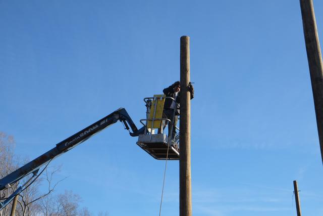
Overhead line going up
April 2017: With warmer weather, work has resumed on the overhead
line aspect of Elevating the Collection. Many poles were set last fall.
In this second phase of the project, we are putting up the cross-spans.
First, spans are assembled on the ground:
Since we don't have live wire up here yet, the Ottawa Line Car is a bit
difficult to use. Instead, we have the bucket lift mounted on a flatcar
and propelled by the car-mover. Here an eyebolt has been installed
through new pole E-09 and the previously assembled span is being attached.
|